Car scan tools are essential for diagnosing modern vehicle systems, and mastering their use is critical for automotive technicians. At CAR-SCAN-TOOL.EDU.VN, we provide in-depth training to ensure you can effectively utilize these tools. Our comprehensive programs cover everything from basic code reading to advanced data analysis, enhancing your diagnostic skills and career prospects.
Contents
- 1. Understanding Brake Pedal Position Sensors
- 1.1 The Evolution of Brake Pedal Sensors
- 1.2 How Brake Pedal Position Sensors Work
- 1.3 Importance in Modern Vehicles
- 2. Common Types of Brake Pedal Position Sensors
- 2.1 Position Switches
- 2.2 Pressure Sensors
- 2.3 Load Sensors
- 2.4 Vacuum Sensors
- 3. Diagnosing Brake Pedal Position Sensor Issues
- 3.1 Visual Inspection
- 3.2 Code Reading
- 3.3 Data Analysis
- 3.4 Wiring Diagram Checks
- 3.5 Component Testing
- 4. Scan Tool Diagnostics for Brake Pedal Position Sensors
- 4.1 Reading Codes
- 4.2 Accessing PIDs
- 4.3 Advanced Functions
- 4.4 Interpreting Data
- 5. Common Diagnostic Trouble Codes (DTCs)
- 5.1 Code C1267 (Toyota)
- 5.2 Code C0277 (GM)
- 5.3 Other Common Codes
- 6. Installation and Calibration Procedures
- 6.1 Installation
- 6.2 Calibration
- 6.3 One-Time Adjustment Sensors
- 6.4 Checking for Correct Operation
- 7. The Role of Training in Mastering Scan Tool Diagnostics
- 7.1 The Importance of Training
- 7.2 CAR-SCAN-TOOL.EDU.VN Training Programs
- 7.3 Benefits of Training
- 8. The Future of Brake System Diagnostics
- 8.1 Advanced Sensors
- 8.2 Data Analysis
- 8.3 Remote Diagnostics
- 9. Why Choose CAR-SCAN-TOOL.EDU.VN for Your Training Needs?
- 9.1 Comprehensive Curriculum
- 9.2 Experienced Instructors
- 9.3 Hands-On Training
- 9.4 Flexible Learning Options
- 9.5 Industry-Recognized Certification
- 10. Frequently Asked Questions (FAQs)
1. What Information Can Professional Tools Read From Brake Pedal Position Sensors?
Yes, professional car scan tools can indeed read data related to brake pedal position sensors. These tools display a wealth of information, including the degree to which the brake pedal is depressed, the rate of change when the pedal is pushed, and voltage readings to and from the sensor. This data is vital for diagnosing issues within the braking system and related safety features.
Expanding on this, modern vehicles rely heavily on brake pedal position sensors to provide critical data for various systems, including ABS, stability control, regenerative braking in hybrids and EVs, and ADAS features like automatic emergency braking. Professional scan tools enable technicians to access and interpret this data, which is essential for accurate diagnostics and effective repairs.
2. Why Is the Brake Pedal Position Sensor Important?
The brake pedal position sensor provides essential information about the driver’s braking behavior, which is crucial for modern vehicle safety and control systems. It has evolved from a simple on/off switch to a sophisticated sensor that measures the pedal’s position and the rate at which it is pressed.
- ABS (Anti-lock Braking System): The sensor provides data that helps the ABS determine when to modulate brake pressure to prevent wheel lockup during hard braking.
- Stability Control: The sensor’s input, along with data from wheel speed, lateral acceleration, and yaw sensors, allows the stability control system to detect and correct skids.
- Regenerative Braking: In hybrid and electric vehicles, the brake pedal position sensor helps manage the transition between regenerative braking (using the motor to slow the vehicle and recharge the battery) and traditional friction braking.
- ADAS (Advanced Driver-Assistance Systems): Automatic emergency braking systems rely on the brake pedal position sensor to determine when the driver is initiating braking and to supplement that braking if necessary to avoid a collision.
3. What Are the Symptoms of a Faulty Brake Pedal Position Sensor?
A faulty brake pedal position sensor can manifest in several noticeable symptoms, affecting vehicle performance and safety systems. These include:
- Unable to Start the Engine: The sensor may be part of the starting circuit, preventing the engine from cranking if it is not functioning correctly.
- Unable to Shift Out of Park: The brake-shift interlock system relies on the brake pedal position sensor to allow the driver to shift out of park.
- ABS and Stability Control Disabled: Faulty sensor data can cause the ABS and stability control systems to be deactivated, compromising safety.
- Cruise Control Issues: The cruise control system may not engage or may disengage unexpectedly if the brake pedal position sensor is malfunctioning.
- Brake Lights Problems: The brake lights may stay on continuously, draining the battery, or they may not illuminate when the pedal is pressed.
4. How Are Brake Pedal Position Sensors Connected to the Vehicle’s Systems?
Brake pedal position sensors are typically connected to the ABS module, which then shares the data with other modules like the engine control module (ECM), body control module (BCM), and electric power steering (EPS) module via the CAN bus.
- ABS Module: The primary connection point for the brake pedal position sensor.
- CAN Bus: The communication network that allows different modules in the vehicle to share data.
- ECM: Uses brake pedal position data for engine management and cruise control functions.
- BCM: Controls various body functions, including brake lights.
- EPS: Can use brake pedal position data to adjust steering assist during braking.
5. Where Can I Find Wiring Diagrams for Brake Pedal Position Sensors?
Wiring diagrams for brake pedal position sensors are typically found in the ABS/Brakes section of the vehicle’s wiring diagrams. These diagrams provide essential information about the sensor’s pinout and circuit connections.
- ABS/Brakes Section: The dedicated section in the wiring diagrams for braking system components.
- Pinout Information: Shows the specific connections for each pin on the sensor.
- Circuit Connections: Details the wiring paths and connections to other modules.
6. What Should I Check When Diagnosing a Brake Pedal Position Sensor Circuit?
When diagnosing a brake pedal position sensor circuit, it is crucial to check the condition of the circuit, including the voltage signal and ground connections. Most of these sensors use a five-volt signal or less.
- Voltage Signal: Verify that the sensor is receiving the correct voltage signal (typically 5V or less).
- Ground Connection: Ensure that the sensor has a good ground connection to prevent faulty readings.
- Resistance: Check for high resistance in the circuit, which can cause inaccurate data.
7. How Do Scan Tools Help Diagnose Brake Pedal Position Sensors?
Scan tools provide access to codes and PIDs (Parameter Identification Data) related to the brake pedal position sensor, allowing technicians to monitor the sensor’s performance and identify faults.
- Codes: Diagnostic trouble codes (DTCs) that indicate specific issues with the sensor or its circuit.
- PIDs: Real-time data parameters, such as voltage readings, pedal position, and force measurements.
- Data Analysis: Scan tools allow technicians to analyze the data and identify deviations from normal values.
8. What Are Some Common Codes Associated With Brake Pedal Position Sensors?
Common codes associated with brake pedal position sensors include C1267 (pedal force switch malfunction) on Toyota vehicles and C0277 (brake pedal position sensor circuit malfunction) on GM vehicles. These codes can indicate various issues, such as shorts, opens, or high resistance in the sensor circuit.
- C1267 (Toyota): Pedal force switch malfunction.
- C0277 (GM): Brake pedal position sensor circuit malfunction.
- Additional Digits: Some manufacturers add additional digits to expand the code and provide more specific information (e.g., C0277-06 for shorts in the 5-volt reference circuit).
9. Do Brake Pedal Position Sensors Require Calibration After Installation?
Yes, some brake pedal position sensors require calibration using a scan tool after installation. If a sensor is not calibrated correctly, it may generate a code for incorrect or implausible data.
- Calibration Procedure: Follow the manufacturer’s recommended calibration procedure using a compatible scan tool.
- Incorrect Data: Failure to calibrate the sensor can result in inaccurate data and system malfunctions.
- Code Generation: An uncalibrated sensor may trigger diagnostic trouble codes.
10. What Training Is Available to Improve My Skills in Diagnosing Brake Systems?
CAR-SCAN-TOOL.EDU.VN offers comprehensive training programs to enhance your skills in diagnosing brake systems and utilizing scan tools effectively. Our courses cover everything from basic sensor diagnostics to advanced data analysis and calibration procedures.
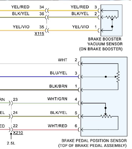 Ford Brake Pedal Switch with Vacuum Sensor
1. Understanding Brake Pedal Position Sensors
The evolution of brake pedal sensors from simple on/off switches to sophisticated devices that measure pedal position and force has revolutionized vehicle safety and control systems. Understanding the function and operation of these sensors is crucial for effective diagnostics.
1.1 The Evolution of Brake Pedal Sensors
In the past, brake pedal switches were simple on/off devices that activated the brake lights and, in some cases, disengaged cruise control. Modern vehicles, however, require more detailed information about the driver’s braking behavior for systems like ABS, stability control, and ADAS. This has led to the development of brake pedal position sensors that provide continuous data about the pedal’s position and the rate at which it is pressed.
1.2 How Brake Pedal Position Sensors Work
Brake pedal position sensors use various technologies to measure the pedal’s position, including potentiometers, Hall effect sensors, and load cells. These sensors convert the mechanical movement of the pedal into an electrical signal that can be interpreted by the vehicle’s control modules.
1.3 Importance in Modern Vehicles
The data from brake pedal position sensors is critical for a wide range of vehicle systems:
- ABS: Prevents wheel lockup during hard braking.
- Stability Control: Helps maintain vehicle stability during skids.
- Regenerative Braking: Manages the transition between regenerative and friction braking in hybrids and EVs.
- ADAS: Provides input for automatic emergency braking and other driver-assistance features.
- Start/Stop Systems: Ensures smooth and safe engine restarts.
2. Common Types of Brake Pedal Position Sensors
Different manufacturers and vehicle models use various types of brake pedal position sensors. Understanding the characteristics of each type is essential for accurate diagnostics and repairs.
2.1 Position Switches
Position switches are basic on/off devices that indicate whether the brake pedal is pressed or not. They are typically used for brake light activation and cruise control disengagement.
2.2 Pressure Sensors
Pressure sensors measure the pressure in the brake lines, providing additional information about the driver’s braking effort. These sensors are often used in conjunction with position sensors to improve the accuracy of braking system control.
2.3 Load Sensors
Load sensors measure the force applied to the brake pedal, providing a direct indication of the driver’s braking intent. These sensors are commonly used in vehicles with advanced braking systems, such as those with automatic emergency braking.
2.4 Vacuum Sensors
Some manufacturers, like Ford, use vacuum sensors to measure the vacuum at the brake booster, providing an indirect indication of brake pedal position.
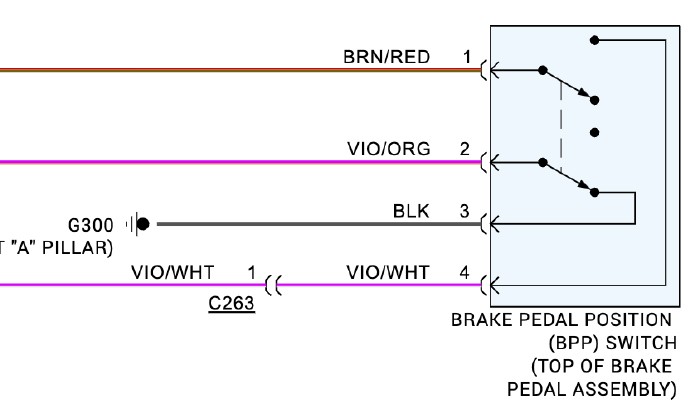 Simple Position Switch
3. Diagnosing Brake Pedal Position Sensor Issues
Diagnosing issues with brake pedal position sensors requires a systematic approach, including visual inspection, code reading, and data analysis.
3.1 Visual Inspection
Begin by visually inspecting the sensor and its wiring for any signs of damage, such as corrosion, frayed wires, or loose connections.
3.2 Code Reading
Use a scan tool to read any diagnostic trouble codes (DTCs) related to the brake pedal position sensor. These codes can provide valuable clues about the nature of the problem.
3.3 Data Analysis
Use the scan tool to monitor the sensor’s data parameters (PIDs) while operating the brake pedal. Look for any abnormalities, such as erratic readings, missing data, or values that are outside the expected range.
3.4 Wiring Diagram Checks
Consult the vehicle’s wiring diagrams to verify the sensor’s wiring connections and check for any shorts, opens, or high resistance in the circuit.
3.5 Component Testing
Use a multimeter to test the sensor’s voltage signal, ground connection, and resistance. Compare your measurements to the manufacturer’s specifications to determine if the sensor is functioning correctly.
4. Scan Tool Diagnostics for Brake Pedal Position Sensors
Scan tools are essential for diagnosing brake pedal position sensor issues, providing access to codes, PIDs, and advanced diagnostic functions.
4.1 Reading Codes
Scan tools can retrieve diagnostic trouble codes (DTCs) related to the brake pedal position sensor, helping technicians pinpoint the source of the problem.
4.2 Accessing PIDs
Scan tools allow technicians to monitor the sensor’s data parameters (PIDs) in real-time, providing valuable insights into its performance. Common PIDs include:
- Brake Pedal Position: The percentage of pedal travel.
- Brake Pedal Force: The amount of force applied to the pedal.
- Sensor Voltage: The voltage signal from the sensor.
4.3 Advanced Functions
Some scan tools offer advanced functions, such as:
- Calibration: Allows technicians to calibrate the sensor after installation.
- Actuation Tests: Enables technicians to activate the sensor and verify its response.
- Data Logging: Records sensor data for later analysis.
4.4 Interpreting Data
Interpreting the data from a scan tool requires a thorough understanding of the brake system and the sensor’s operation. Technicians should look for any abnormalities, such as erratic readings, missing data, or values that are outside the expected range.
5. Common Diagnostic Trouble Codes (DTCs)
Understanding common diagnostic trouble codes (DTCs) associated with brake pedal position sensors is essential for efficient and accurate diagnostics.
5.1 Code C1267 (Toyota)
Code C1267 on Toyota vehicles indicates a malfunction in the brake pedal load sensing switch. The criteria for setting this code include:
- An open or short in the brake pedal load sensing switch continues for 0.3 seconds or more.
- Immediately after the engine switch is turned on (IG), the brake pedal load sensing switch is ON, and the stop light switch is OFF for 10 seconds or more.
- While the vehicle speed changes from 0 to 18 mph, the condition that the brake pedal load sensing switch remains ON occurs five times in succession.
- With the stop light switch ON, the brake pedal load sensing switch OFF, and the master cylinder pressure 870 psi or more, the deceleration is 0.4 G or more for 1 second or more.
- With the stop light switch ON, the brake pedal load sensing switch OFF, and the master cylinder pressure 870 psi or more, the vehicle speed is 0 mph for 5 seconds or more.
5.2 Code C0277 (GM)
Code C0277 on GM vehicles indicates a brake pedal position sensor circuit malfunction. Additional digits may be added to the code to provide more specific information, such as:
- C0277-06: Shorts, opens, or high resistance in the 5-volt reference circuit.
- C0277-07: Issues with the signal circuit.
5.3 Other Common Codes
Other common codes associated with brake pedal position sensors include:
- P0703: Brake Switch Input Circuit Malfunction
- P0719: Brake Switch B Circuit Low
- P0724: Brake Switch B Circuit High
6. Installation and Calibration Procedures
Proper installation and calibration are essential for ensuring the correct operation of brake pedal position sensors.
6.1 Installation
Follow the manufacturer’s instructions for installing the brake pedal position sensor. Some sensors are shipped in a locked position and require a specific procedure to unlock them.
6.2 Calibration
Some sensors require calibration using a scan tool after installation. This process ensures that the sensor is properly aligned and providing accurate data.
6.3 One-Time Adjustment Sensors
Some sensors have a “one-time” adjustment feature that cannot be reset. If these sensors are removed from the vehicle, they may not be reusable.
6.4 Checking for Correct Operation
After installation and calibration, verify that the sensor is functioning correctly by monitoring its data parameters with a scan tool and checking for any diagnostic trouble codes.
7. The Role of Training in Mastering Scan Tool Diagnostics
Mastering scan tool diagnostics for brake systems requires comprehensive training and hands-on experience.
7.1 The Importance of Training
Proper training is essential for understanding the complex systems in modern vehicles and using scan tools effectively. Training programs should cover:
- Basic electrical theory
- Brake system operation
- Scan tool functions and features
- Diagnostic procedures
- Data analysis techniques
7.2 CAR-SCAN-TOOL.EDU.VN Training Programs
CAR-SCAN-TOOL.EDU.VN offers comprehensive training programs designed to enhance your skills in scan tool diagnostics and brake system repair. Our courses cover:
- Basic scan tool operation
- Advanced diagnostic techniques
- Data analysis and interpretation
- Calibration procedures
- Hands-on practice
7.3 Benefits of Training
Completing a training program can provide numerous benefits, including:
- Improved diagnostic accuracy
- Increased efficiency
- Enhanced career opportunities
- Higher earning potential
8. The Future of Brake System Diagnostics
The future of brake system diagnostics is likely to involve more sophisticated sensors, advanced data analysis techniques, and remote diagnostic capabilities.
8.1 Advanced Sensors
Future brake systems may incorporate more advanced sensors, such as:
- Wheel speed sensors with integrated accelerometers
- Brake pad wear sensors
- Brake fluid condition sensors
8.2 Data Analysis
Advanced data analysis techniques, such as machine learning and artificial intelligence, will play an increasing role in brake system diagnostics. These techniques can be used to:
- Identify subtle patterns and anomalies in sensor data
- Predict component failures
- Optimize braking system performance
8.3 Remote Diagnostics
Remote diagnostic capabilities will allow technicians to diagnose and repair brake systems from remote locations, reducing downtime and improving customer service.
9. Why Choose CAR-SCAN-TOOL.EDU.VN for Your Training Needs?
CAR-SCAN-TOOL.EDU.VN is committed to providing high-quality training that meets the evolving needs of the automotive industry.
9.1 Comprehensive Curriculum
Our training programs cover a wide range of topics, from basic scan tool operation to advanced diagnostic techniques.
9.2 Experienced Instructors
Our instructors are experienced automotive technicians with extensive knowledge of brake systems and scan tool diagnostics.
9.3 Hands-On Training
Our programs emphasize hands-on training, allowing you to apply your knowledge in a real-world setting.
9.4 Flexible Learning Options
We offer flexible learning options, including online courses, on-site training, and customized programs.
9.5 Industry-Recognized Certification
Upon completion of our training programs, you will receive an industry-recognized certification that demonstrates your skills and knowledge.
10. Frequently Asked Questions (FAQs)
Here are some frequently asked questions about brake pedal position sensors and scan tool diagnostics:
1. What type of scan tool do I need to read brake pedal position sensor data?
A professional-grade scan tool with ABS and stability control diagnostic capabilities is required.
2. Can I use a basic code reader to diagnose brake pedal position sensor issues?
A basic code reader may not provide enough information to diagnose complex issues with brake pedal position sensors. A more advanced scan tool is recommended.
3. How often should I calibrate my brake pedal position sensor?
Calibration is typically only required after replacing the sensor.
4. What are the benefits of training in scan tool diagnostics?
Training can improve your diagnostic accuracy, increase your efficiency, and enhance your career opportunities.
5. Does CAR-SCAN-TOOL.EDU.VN offer online training courses?
Yes, we offer a variety of online training courses to fit your schedule and learning preferences.
6. How long does it take to complete a CAR-SCAN-TOOL.EDU.VN training program?
The duration of our training programs varies depending on the course and your learning pace.
7. What is the cost of CAR-SCAN-TOOL.EDU.VN training programs?
The cost of our training programs varies depending on the course and the level of certification. Contact us for more information.
8. What type of support is available to CAR-SCAN-TOOL.EDU.VN students?
We offer a variety of support resources, including online forums, live Q&A sessions, and one-on-one mentoring.
9. Can I get certified after completing a CAR-SCAN-TOOL.EDU.VN training program?
Yes, upon completion of our training programs, you will receive an industry-recognized certification that demonstrates your skills and knowledge.
10. How do I enroll in a CAR-SCAN-TOOL.EDU.VN training program?
Contact us today to learn more about our training programs and enroll in a course.
Ready to elevate your automotive diagnostic skills? Contact CAR-SCAN-TOOL.EDU.VN today and unlock your full potential in the world of automotive technology. Don’t let outdated skills hold you back. Our expert-led remote technician courses offer the flexibility and in-depth knowledge you need to excel. We are available via Whatsapp at +1 (641) 206-8880 or visit our website CAR-SCAN-TOOL.EDU.VN. Our US support office is located at 555 Automotive Way, Suite 100, Los Angeles, CA 90017, United States. Reach out now and take the first step towards a brighter future in automotive diagnostics, ensuring you’re equipped to tackle any challenge with confidence and expertise through our cutting-edge remote technician education.