Are you looking to master Variable Valve Timing (VVT) system diagnostics? Can Professional Tools Test Solenoids And Sensors Within The VVT System? The answer is a resounding yes! Professional diagnostic tools are essential for accurately testing solenoids and sensors within the VVT system, ensuring optimal engine performance. CAR-SCAN-TOOL.EDU.VN offers comprehensive training to help you master these tools and excel in automotive diagnostics, giving you the expertise to interpret complex data and troubleshoot VVT issues efficiently. Through our remote technician education, you will learn to use advanced automotive scanner training to enhance your diagnostic skills and career prospects.
Contents
- 1. Understanding the VVT System and Its Importance
- 1.1 Benefits of VVT
- 1.2 Key Components of the VVT System
- 2. Why Professional Tools Are Essential for VVT Diagnostics
- 2.1 Common VVT Problems
- 2.2 The Role of Diagnostic Trouble Codes (DTCs)
- 3. Types of Professional Tools for Testing VVT Systems
- 3.1 OBD-II Scanners
- Key Features of OBD-II Scanners
- 3.2 Advanced Scan Tools
- Examples of Advanced Scan Tools
- 3.3 Multimeters
- Using a Multimeter for VVT Diagnostics
- 3.4 Oscilloscopes
- Applications of Oscilloscopes in VVT Diagnostics
- 4. Testing VVT Solenoids with Professional Tools
- 4.1 Visual Inspection
- 4.2 Electrical Testing with a Multimeter
- 4.3 Activation Test with a Scan Tool
- Steps for Activation Test
- 4.4 Advanced Testing with an Oscilloscope
- Analyzing the Waveform
- 5. Testing VVT Sensors with Professional Tools
- 5.1 Visual Inspection
- 5.2 Checking Sensor Signal with a Scan Tool
- Steps for Checking Sensor Signal
- 5.3 Advanced Testing with an Oscilloscope
- Analyzing the Waveform
- 5.4 Testing Sensor Resistance with a Multimeter
- 5.5 Checking for Signal Interference
- Steps for Checking Signal Interference
- 6. The Importance of Live Data Monitoring in VVT Diagnostics
- 6.1 Key Data Parameters to Monitor
- 6.2 Interpreting Live Data
- 6.3 Using Graphing Features
- 7. Case Studies: Real-World VVT Diagnostic Scenarios
- 7.1 Case Study 1: P0011 Code on a Honda Civic
- Diagnostic Steps
- Diagnosis and Solution
- 7.2 Case Study 2: P0016 Code on a Toyota Camry
- Diagnostic Steps
- Diagnosis and Solution
- 8. The Role of Training and Certification in VVT Diagnostics
- 8.1 Benefits of Training
- 8.2 Certifications
- Examples of Certifications
- 8.3 CAR-SCAN-TOOL.EDU.VN: Your Partner in VVT Diagnostic Training
- 9. Preventive Maintenance for VVT Systems
- 9.1 Oil Changes
- 9.2 Filter Replacements
- 9.3 Timing Belt/Chain Replacement
- 9.4 VVT Solenoid Cleaning
- 9.5 Regular Inspections
- 10. Future Trends in VVT Diagnostics
- 10.1 Advanced Diagnostic Algorithms
- 10.2 Remote Diagnostics
- 10.3 Artificial Intelligence (AI)
- 10.4 Augmented Reality (AR)
- FAQ: Frequently Asked Questions About VVT Diagnostics
- Conclusion
1. Understanding the VVT System and Its Importance
What exactly is the Variable Valve Timing (VVT) system and why is it so crucial for modern engines? The VVT system is an innovative technology designed to optimize engine performance, fuel efficiency, and reduce emissions by dynamically adjusting the timing of the intake and exhaust valves.
The VVT system adjusts valve timing based on various factors such as engine speed, load, and temperature. This precise control allows the engine to operate more efficiently across different driving conditions. For example, at low speeds, the VVT system can retard the intake valve timing to improve idle stability and low-end torque. At high speeds, it can advance the intake valve timing to increase horsepower and overall performance.
Alt text: Diagram illustrating the components and functionality of a Variable Valve Timing (VVT) system, highlighting its role in optimizing engine performance.
1.1 Benefits of VVT
The benefits of VVT include:
- Improved Fuel Efficiency: By optimizing valve timing, the engine consumes fuel more efficiently, resulting in better mileage. According to a study by the U.S. Department of Energy, VVT systems can improve fuel economy by up to 7%.
- Enhanced Engine Performance: VVT systems boost both low-end torque and high-end horsepower, providing a more responsive and enjoyable driving experience.
- Reduced Emissions: Optimized combustion reduces harmful emissions, contributing to a cleaner environment.
- Smoother Engine Operation: VVT helps maintain a smoother idle and reduces engine knocking, enhancing overall engine reliability and longevity.
1.2 Key Components of the VVT System
Several key components work together to make the VVT system function effectively:
- Camshaft Position Sensor (CMP): Monitors the position of the camshaft and sends this information to the Engine Control Module (ECM).
- Crankshaft Position Sensor (CKP): Monitors the position of the crankshaft and sends data to the ECM.
- VVT Solenoids: Control the flow of oil to the VVT actuator, adjusting the camshaft timing.
- VVT Actuator: Physically adjusts the camshaft position based on signals from the ECM and VVT solenoids.
- Engine Control Module (ECM): The brain of the system, processing data from various sensors and controlling the VVT solenoids to optimize valve timing.
2. Why Professional Tools Are Essential for VVT Diagnostics
Why can’t you rely solely on visual inspections or basic tools when diagnosing VVT issues? Professional diagnostic tools provide the accuracy, data, and capabilities needed to effectively troubleshoot the complex VVT system. Here’s why they are indispensable:
- Accuracy: Professional tools provide precise readings from sensors and actuators, allowing technicians to identify even minor deviations from expected values.
- Data Analysis: These tools can display live data streams, allowing technicians to monitor the VVT system in real-time and identify anomalies.
- Efficiency: Quick and accurate diagnostics save time and reduce the chances of misdiagnosis, leading to faster and more cost-effective repairs.
- Comprehensive Testing: Professional tools can perform specific tests on VVT components, such as solenoid activation tests and actuator response tests, which are impossible with basic tools.
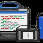
Alt text: Advanced car scan tool displaying live data streams, essential for accurate diagnostics of complex VVT systems and component testing.
2.1 Common VVT Problems
Understanding the common problems that can plague a VVT system is the first step in effective diagnostics:
- Faulty Sensors: The Camshaft Position Sensor (CMP) and Crankshaft Position Sensor (CKP) can fail, providing incorrect data to the ECM.
- Solenoid Malfunctions: VVT solenoids can become clogged, stuck, or electrically faulty, preventing proper oil flow to the VVT actuator.
- Actuator Issues: The VVT actuator itself can fail mechanically, preventing the camshaft from adjusting properly.
- Oil Pressure Problems: Low oil pressure or contaminated oil can affect the performance of the VVT system.
- Timing Component Wear: A worn timing chain or belt can cause timing discrepancies, leading to VVT problems.
2.2 The Role of Diagnostic Trouble Codes (DTCs)
How do Diagnostic Trouble Codes (DTCs) fit into the diagnostic process? DTCs are codes stored in the ECM that indicate a problem within the VVT system or other engine components. Some common DTCs related to VVT include:
- P0011: “A” Camshaft Position – Timing Over-Advanced or System Performance (Bank 1)
- P0012: “A” Camshaft Position – Timing Over-Retarded (Bank 1)
- P0016: Crankshaft Position – Camshaft Position Correlation (Bank 1 Sensor A)
- P0017: Crankshaft Position – Camshaft Position Correlation (Bank 1 Sensor B)
These codes provide a starting point for diagnosing VVT issues, but they don’t tell the whole story. Further testing with professional tools is essential to pinpoint the exact cause of the problem.
3. Types of Professional Tools for Testing VVT Systems
What kinds of professional tools are available for VVT diagnostics? Several types of tools are essential for effectively diagnosing and repairing VVT systems.
3.1 OBD-II Scanners
OBD-II scanners are the foundation of modern automotive diagnostics. These tools plug into the vehicle’s OBD-II port and allow technicians to read Diagnostic Trouble Codes (DTCs), view live data, and perform basic tests. Advanced OBD-II scanners offer additional features, such as bidirectional control and component testing.
Key Features of OBD-II Scanners
- DTC Reading and Clearing: Retrieves and clears diagnostic trouble codes.
- Live Data Streaming: Displays real-time data from sensors and actuators.
- Freeze Frame Data: Captures data when a DTC is set, providing valuable diagnostic information.
- Bidirectional Control: Allows technicians to activate and control certain components for testing purposes.
3.2 Advanced Scan Tools
Advanced scan tools offer more sophisticated capabilities than basic OBD-II scanners. These tools often include features such as:
- Enhanced Diagnostics: Access to manufacturer-specific diagnostic data and tests.
- Component Testing: Ability to perform specific tests on individual VVT components.
- Graphing: Visual representation of live data streams for easier analysis.
- Software Updates: Regular updates to support new vehicle models and diagnostic procedures.
Examples of Advanced Scan Tools
- Autel MaxiSys MS908S Pro: A comprehensive diagnostic tool with advanced features for VVT system testing.
- Snap-on VERUS Edge: An advanced scan tool known for its user-friendly interface and powerful diagnostic capabilities.
- Launch X431 V+: A versatile scan tool with a wide range of diagnostic functions and vehicle coverage.
3.3 Multimeters
A multimeter is an essential tool for any automotive technician. It can be used to measure voltage, current, and resistance, which are crucial for diagnosing electrical problems within the VVT system.
Using a Multimeter for VVT Diagnostics
- Voltage Testing: Check the voltage supply to VVT solenoids and sensors.
- Continuity Testing: Verify the continuity of wiring harnesses and connectors.
- Resistance Testing: Measure the resistance of VVT solenoids to check for internal faults.
3.4 Oscilloscopes
An oscilloscope is a powerful tool that displays electrical signals as waveforms. This allows technicians to visualize the behavior of sensors and actuators over time, making it easier to identify intermittent problems and signal anomalies.
Applications of Oscilloscopes in VVT Diagnostics
- Sensor Signal Analysis: Analyze the waveforms of CMP and CKP sensors to check for signal irregularities.
- Solenoid Response Testing: Observe the response time and behavior of VVT solenoids when activated.
- Electrical Noise Detection: Identify electrical noise or interference that could be affecting the VVT system.
4. Testing VVT Solenoids with Professional Tools
How do you use professional tools to specifically test VVT solenoids? VVT solenoids are critical components that control the flow of oil to the VVT actuator. Testing these solenoids is essential for diagnosing VVT problems.
4.1 Visual Inspection
Start with a visual inspection of the VVT solenoids. Look for signs of damage, such as cracks, leaks, or corrosion. Check the electrical connectors for proper engagement and any signs of damage.
4.2 Electrical Testing with a Multimeter
Use a multimeter to perform the following electrical tests on the VVT solenoids:
- Resistance Test: Measure the resistance of the solenoid coil. Compare the reading to the manufacturer’s specifications. A reading outside the specified range indicates a faulty solenoid.
- Voltage Test: Check the voltage supply to the solenoid. Ensure that the solenoid is receiving the correct voltage when activated.
- Continuity Test: Verify the continuity of the wiring between the ECM and the solenoid.
4.3 Activation Test with a Scan Tool
Use a scan tool to perform an activation test on the VVT solenoids. This test allows you to manually activate the solenoid and observe its response.
Steps for Activation Test
- Connect the scan tool to the vehicle’s OBD-II port.
- Navigate to the VVT system diagnostic menu.
- Select the “Solenoid Activation Test” option.
- Follow the scan tool’s instructions to activate the solenoid.
- Listen for a clicking sound, indicating that the solenoid is activating.
- Monitor the engine’s response to the solenoid activation.
If the solenoid does not activate or the engine does not respond as expected, the solenoid may be faulty.
4.4 Advanced Testing with an Oscilloscope
An oscilloscope can provide more detailed information about the VVT solenoid’s performance. Use an oscilloscope to observe the solenoid’s current waveform when activated.
Analyzing the Waveform
- Response Time: Check the time it takes for the solenoid to fully activate. A slow response time indicates a problem.
- Current Draw: Monitor the current draw of the solenoid. An abnormally high or low current draw indicates a fault.
- Signal Noise: Look for any noise or interference in the signal.
5. Testing VVT Sensors with Professional Tools
How can professional tools help you diagnose issues with VVT sensors? VVT sensors, such as the Camshaft Position Sensor (CMP) and Crankshaft Position Sensor (CKP), provide critical data to the ECM. Testing these sensors is crucial for accurate VVT diagnostics.
5.1 Visual Inspection
Begin with a visual inspection of the VVT sensors. Look for signs of damage, such as cracks, breaks, or corrosion. Check the electrical connectors for proper engagement and any signs of damage.
5.2 Checking Sensor Signal with a Scan Tool
Use a scan tool to monitor the sensor signals in real-time.
Steps for Checking Sensor Signal
- Connect the scan tool to the vehicle’s OBD-II port.
- Navigate to the VVT system diagnostic menu.
- Select the “Live Data” or “Data Stream” option.
- Select the CMP and CKP sensor signals.
- Monitor the sensor signals while the engine is running.
The sensor signals should be within the manufacturer’s specified range and respond appropriately to changes in engine speed and load.
5.3 Advanced Testing with an Oscilloscope
An oscilloscope can provide a more detailed analysis of the sensor signals.
Analyzing the Waveform
- Signal Amplitude: Check the voltage level of the signal.
- Signal Frequency: Verify the frequency of the signal.
- Signal Shape: Look for any irregularities in the shape of the waveform.
- Missing Pulses: Identify any missing pulses in the signal, which indicate a problem with the sensor or its reluctor wheel.
5.4 Testing Sensor Resistance with a Multimeter
Use a multimeter to measure the resistance of the sensor. Compare the reading to the manufacturer’s specifications. A reading outside the specified range indicates a faulty sensor.
5.5 Checking for Signal Interference
Electrical interference can affect the accuracy of sensor signals. Use an oscilloscope to check for any noise or interference in the signal.
Steps for Checking Signal Interference
- Connect the oscilloscope to the sensor signal wire.
- Start the engine and monitor the signal.
- Look for any erratic spikes or dips in the waveform, which indicate interference.
6. The Importance of Live Data Monitoring in VVT Diagnostics
Why is monitoring live data essential for effective VVT diagnostics? Live data monitoring allows technicians to observe the VVT system in real-time, providing valuable insights into its operation.
6.1 Key Data Parameters to Monitor
- Camshaft Position Angle: The actual position of the camshaft, as reported by the CMP sensor.
- Crankshaft Position Angle: The position of the crankshaft, as reported by the CKP sensor.
- VVT Solenoid Duty Cycle: The percentage of time that the VVT solenoid is activated.
- Engine Speed (RPM): The speed of the engine.
- Engine Load: The amount of load on the engine.
- Oil Temperature: The temperature of the engine oil.
6.2 Interpreting Live Data
By monitoring these data parameters, technicians can identify anomalies and diagnose VVT problems. For example, if the camshaft position angle does not match the desired angle, it could indicate a problem with the VVT solenoid or actuator. If the VVT solenoid duty cycle is abnormally high or low, it could indicate an electrical fault or a problem with the oil supply.
6.3 Using Graphing Features
Many advanced scan tools offer graphing features that allow technicians to visualize live data streams. Graphing can make it easier to identify trends and patterns in the data, leading to a more accurate diagnosis.
Alt text: Image representing automotive diagnostic training, emphasizing the importance of skilled technicians in using diagnostic tools and interpreting complex data.
7. Case Studies: Real-World VVT Diagnostic Scenarios
How can you apply these diagnostic techniques in real-world situations? Let’s explore some case studies to illustrate how professional tools can be used to diagnose VVT problems.
7.1 Case Study 1: P0011 Code on a Honda Civic
A 2016 Honda Civic came into the shop with a P0011 code (“A” Camshaft Position – Timing Over-Advanced or System Performance (Bank 1)). The technician used a scan tool to read the code and monitor live data.
Diagnostic Steps
- Visual Inspection: The technician started with a visual inspection of the VVT solenoid and sensor, checking for any obvious damage.
- Live Data Monitoring: The technician monitored the camshaft position angle and VVT solenoid duty cycle. They noticed that the camshaft position angle was consistently higher than the desired angle, and the VVT solenoid duty cycle was higher than normal.
- Solenoid Activation Test: The technician performed a solenoid activation test with the scan tool. The solenoid activated, but the camshaft position angle did not change as expected.
- Resistance Test: The technician used a multimeter to measure the resistance of the solenoid. The resistance was within the manufacturer’s specifications.
Diagnosis and Solution
Based on these tests, the technician suspected a problem with the VVT actuator. They removed the actuator and found that it was clogged with sludge. The actuator was cleaned, and the engine oil was changed. After reassembling the VVT system, the P0011 code was cleared, and the engine ran smoothly.
7.2 Case Study 2: P0016 Code on a Toyota Camry
A 2018 Toyota Camry came into the shop with a P0016 code (Crankshaft Position – Camshaft Position Correlation (Bank 1 Sensor A)).
Diagnostic Steps
- Visual Inspection: The technician visually inspected the CMP and CKP sensors, checking for any damage or loose connections.
- Live Data Monitoring: The technician monitored the CMP and CKP sensor signals using a scan tool. The signals appeared to be normal.
- Oscilloscope Testing: The technician used an oscilloscope to analyze the CMP and CKP sensor waveforms. They noticed that the CMP signal was slightly out of sync with the CKP signal.
- Timing Chain Inspection: The technician suspected a problem with the timing chain. They removed the valve cover and inspected the timing chain. They found that the timing chain was stretched.
Diagnosis and Solution
The stretched timing chain was causing the camshaft and crankshaft to be out of sync, triggering the P0016 code. The technician replaced the timing chain, and the P0016 code was cleared.
8. The Role of Training and Certification in VVT Diagnostics
Why is specialized training so important for technicians working with VVT systems? Proper training and certification are crucial for technicians to effectively diagnose and repair VVT systems.
8.1 Benefits of Training
- Enhanced Knowledge: Training programs provide technicians with a deep understanding of VVT systems, including their components, operation, and diagnostic procedures.
- Improved Skills: Hands-on training allows technicians to develop the skills needed to use diagnostic tools effectively and perform accurate tests.
- Increased Confidence: With proper training, technicians gain the confidence to tackle complex VVT diagnostic challenges.
- Career Advancement: Technicians with specialized training are more valuable to employers and have greater opportunities for career advancement.
8.2 Certifications
Several certifications are available for automotive technicians, including those that focus on engine performance and diagnostics. These certifications demonstrate a technician’s knowledge and skills in VVT diagnostics.
Examples of Certifications
- ASE (Automotive Service Excellence) Certification: ASE offers certifications in various areas, including engine performance and advanced engine performance.
- Manufacturer-Specific Certifications: Many vehicle manufacturers offer certifications for technicians who specialize in their vehicles.
8.3 CAR-SCAN-TOOL.EDU.VN: Your Partner in VVT Diagnostic Training
How can CAR-SCAN-TOOL.EDU.VN help you become a VVT diagnostic expert? CAR-SCAN-TOOL.EDU.VN offers comprehensive training programs designed to help technicians master VVT diagnostics. Our courses cover:
- VVT System Fundamentals: Learn the basics of VVT systems, including their components and operation.
- Diagnostic Tool Usage: Master the use of OBD-II scanners, advanced scan tools, multimeters, and oscilloscopes.
- Live Data Monitoring: Learn how to monitor and interpret live data to diagnose VVT problems.
- Component Testing: Develop the skills needed to test VVT solenoids, sensors, and actuators.
- Case Studies: Analyze real-world case studies to learn how to apply diagnostic techniques in practical situations.
Our training programs are taught by experienced instructors who are experts in automotive diagnostics. We offer both online and in-person courses to fit your schedule and learning preferences.
9. Preventive Maintenance for VVT Systems
How can preventive maintenance help keep VVT systems running smoothly? Regular preventive maintenance is essential for ensuring the longevity and optimal performance of VVT systems.
9.1 Oil Changes
Regular oil changes are crucial for maintaining the VVT system. Use high-quality engine oil that meets the manufacturer’s specifications. Change the oil at the recommended intervals to prevent oil sludge buildup, which can clog the VVT system.
9.2 Filter Replacements
Replace the oil filter at every oil change. A clogged oil filter can reduce oil pressure, affecting the performance of the VVT system.
9.3 Timing Belt/Chain Replacement
Replace the timing belt or chain at the recommended intervals specified by the manufacturer. A worn timing belt or chain can cause timing discrepancies, leading to VVT problems.
9.4 VVT Solenoid Cleaning
Periodically inspect and clean the VVT solenoids to remove any debris or contamination. Follow the manufacturer’s recommendations for cleaning methods and solvents.
9.5 Regular Inspections
Regularly inspect the VVT system components for any signs of wear or damage. Check the wiring harnesses and connectors for proper engagement and any signs of corrosion.
10. Future Trends in VVT Diagnostics
What does the future hold for VVT diagnostics? The field of automotive diagnostics is constantly evolving, with new technologies and techniques emerging all the time. Here are some future trends to watch for in VVT diagnostics:
10.1 Advanced Diagnostic Algorithms
Automakers are developing more sophisticated diagnostic algorithms that can detect VVT problems more accurately and efficiently. These algorithms use data from multiple sensors and actuators to identify subtle anomalies that might be missed by traditional diagnostic methods.
10.2 Remote Diagnostics
Remote diagnostics allows technicians to diagnose VVT problems remotely, using data transmitted from the vehicle to a central server. This technology can be used to diagnose problems in real-time, without the need for the vehicle to be physically present in the shop.
10.3 Artificial Intelligence (AI)
AI is being used to develop diagnostic tools that can learn from past experiences and make more accurate diagnoses. AI-powered diagnostic tools can analyze large amounts of data to identify patterns and trends that would be difficult for a human technician to detect.
10.4 Augmented Reality (AR)
AR technology is being used to develop diagnostic tools that can overlay diagnostic information onto the technician’s view of the vehicle. This can make it easier to locate and identify VVT components and perform diagnostic tests.
FAQ: Frequently Asked Questions About VVT Diagnostics
Still have questions about VVT diagnostics? Here are some frequently asked questions to help you better understand this complex topic.
1. What is the most common cause of VVT problems?
The most common causes of VVT problems include low or contaminated engine oil, faulty sensors (CMP and CKP), malfunctioning VVT solenoids, and worn timing components.
2. Can a VVT problem cause a check engine light?
Yes, a VVT problem can trigger the check engine light and store Diagnostic Trouble Codes (DTCs) in the ECM.
3. How can I test a VVT solenoid?
You can test a VVT solenoid using a multimeter to measure its resistance and voltage supply, and a scan tool to perform an activation test.
4. What is live data monitoring, and why is it important in VVT diagnostics?
Live data monitoring involves observing real-time data from VVT system sensors and actuators. It’s essential for identifying anomalies and diagnosing VVT problems.
5. What are some common DTCs related to VVT problems?
Common DTCs include P0011, P0012, P0016, and P0017.
6. How often should I change my engine oil to maintain the VVT system?
Follow the manufacturer’s recommended oil change intervals. Use high-quality engine oil that meets the manufacturer’s specifications.
7. What certifications are available for automotive technicians specializing in VVT diagnostics?
ASE certifications in engine performance and advanced engine performance are valuable. Manufacturer-specific certifications are also available.
8. Can I diagnose VVT problems without professional tools?
While visual inspections can help, professional tools are essential for accurate VVT diagnostics due to the complexity of the system.
9. Are there any specific maintenance tasks I should perform to prevent VVT problems?
Regular oil changes, filter replacements, timing belt/chain replacement, and periodic VVT solenoid cleaning can help prevent VVT problems.
10. How can CAR-SCAN-TOOL.EDU.VN help me improve my VVT diagnostic skills?
CAR-SCAN-TOOL.EDU.VN offers comprehensive training programs covering VVT system fundamentals, diagnostic tool usage, live data monitoring, component testing, and case studies.
Conclusion
Mastering VVT diagnostics is essential for any automotive technician looking to stay ahead in today’s rapidly evolving industry. Professional tools are indispensable for accurately testing solenoids and sensors within the VVT system, ensuring optimal engine performance. Remember to leverage diagnostic tools, follow systematic troubleshooting steps, and perform regular preventive maintenance to keep your vehicle running smoothly. With the right training and tools, you can confidently diagnose and repair VVT systems, providing valuable service to your customers and advancing your career.
Ready to elevate your VVT diagnostic skills? Contact CAR-SCAN-TOOL.EDU.VN today at Whatsapp: +1 (641) 206-8880 or visit our website CAR-SCAN-TOOL.EDU.VN to learn more about our comprehensive training programs and unlock your potential in automotive diagnostics. Our office is located at 555 Automotive Way, Suite 100, Los Angeles, CA 90017, United States. Don’t wait—take the next step in your career journey now!