Unlock the full potential of your VCDS with our expert insights on reading data from interior monitoring sensors. CAR-SCAN-TOOL.EDU.VN provides the resources and training you need to diagnose automotive systems effectively. Explore our comprehensive courses for remote technician education and elevate your car diagnostic skills.
Contents
- 1. Can VCDS Read Data From Interior Monitoring Sensors (Ultrasonic/Microwave)?
- 1.1 What types of interior monitoring sensors can VCDS interface with?
- 1.2 How does VCDS communicate with interior monitoring sensors?
- 1.3 Is VCDS the best tool for reading data from these sensors?
- 2. Understanding Interior Monitoring Systems
- 2.1 What are the main components of an interior monitoring system?
- 2.2 How do ultrasonic and microwave sensors work?
- 2.3 What are the common issues with interior monitoring systems?
- 3. How VCDS Interfaces with Interior Monitoring Sensors
- 3.1 What is the communication protocol used by VCDS?
- 3.2 How does VCDS access live data from the sensors?
- 3.3 Can VCDS perform diagnostic tests on interior monitoring sensors?
- 4. What Data Can VCDS Access from Interior Monitoring Sensors?
- 4.1 What live data parameters are available through VCDS?
- 4.2 How does VCDS display diagnostic trouble codes (DTCs)?
- 4.3 Can VCDS access and modify adaptation settings for interior monitoring sensors?
- 5. Benefits of Using VCDS to Read Interior Monitoring Sensor Data
- 5.1 How does VCDS improve diagnostic accuracy for interior monitoring systems?
- 5.2 What are the cost savings associated with using VCDS for diagnostics?
- 5.3 How does VCDS contribute to enhanced security system performance?
- 6. Limitations of VCDS in Reading Interior Monitoring Sensor Data
- 6.1 Are there vehicle models or sensor types that VCDS cannot support?
- 6.2 What are the potential inaccuracies in the data provided by VCDS?
- 6.3 When should alternative diagnostic tools be considered?
- 7. Alternative Tools for Reading Interior Monitoring Sensor Data
- 7.1 What are the dealer-level diagnostic systems for VAG vehicles?
- 7.2 What are the popular aftermarket diagnostic scanners?
- 7.3 How do these tools compare to VCDS in terms of functionality and cost?
- 8. Step-by-Step Guide: Reading Interior Monitoring Sensor Data with VCDS
- 8.1 Connecting VCDS to the vehicle
- 8.2 Accessing the interior monitoring system control module
- 8.3 Reading live data and diagnostic trouble codes (DTCs)
- 9. Advanced VCDS Techniques for Interior Monitoring System Diagnostics
- 9.1 Using adaptation settings to troubleshoot sensor issues
- 9.2 Performing output tests to verify sensor functionality
- 9.3 Analyzing data logs to identify intermittent problems
- 10. Troubleshooting Common Issues When Reading Interior Monitoring Sensor Data
- 10.1 VCDS cannot connect to the control module
- 10.2 Inaccurate or inconsistent sensor readings
- 10.3 False alarms and system malfunctions
- 11. Optimizing VCDS for Enhanced Interior Monitoring System Performance
- 11.1 Updating VCDS software and firmware
- 11.2 Configuring VCDS settings for optimal performance
- 11.3 Creating custom data logging profiles for specific diagnostics
- 12. Expert Tips for Accurate Interior Monitoring Sensor Diagnosis with VCDS
- 12.1 Understanding vehicle-specific wiring diagrams
- 12.2 Using a multimeter to verify sensor signals and power supply
- 12.3 Documenting diagnostic steps and findings
Table of Contents
- Can VCDS Read Data From Interior Monitoring Sensors (ultrasonic/microwave)?
- Understanding Interior Monitoring Systems
- How VCDS Interfaces with Interior Monitoring Sensors
- What Data Can VCDS Access from Interior Monitoring Sensors?
- Benefits of Using VCDS to Read Interior Monitoring Sensor Data
- Limitations of VCDS in Reading Interior Monitoring Sensor Data
- Alternative Tools for Reading Interior Monitoring Sensor Data
- Step-by-Step Guide: Reading Interior Monitoring Sensor Data with VCDS
- Advanced VCDS Techniques for Interior Monitoring System Diagnostics
- Troubleshooting Common Issues When Reading Interior Monitoring Sensor Data
- Optimizing VCDS for Enhanced Interior Monitoring System Performance
- Expert Tips for Accurate Interior Monitoring Sensor Diagnosis with VCDS
- The Future of VCDS and Interior Monitoring System Technology
- Why Choose CAR-SCAN-TOOL.EDU.VN for Automotive Diagnostic Training
- FAQs About VCDS and Interior Monitoring Sensors
1. Can VCDS Read Data From Interior Monitoring Sensors (Ultrasonic/Microwave)?
Yes, VCDS (VAG-COM Diagnostic System) can read data from interior monitoring sensors, including ultrasonic and microwave sensors, in Volkswagen, Audi, Skoda, and SEAT vehicles. This capability allows technicians to diagnose and troubleshoot issues related to the vehicle’s anti-theft system, alarm system, and other interior monitoring functions. VCDS provides access to live data, diagnostic trouble codes (DTCs), and adaptation settings for these sensors, offering valuable insights into their operation.
1.1 What types of interior monitoring sensors can VCDS interface with?
VCDS can interface with various types of interior monitoring sensors, including:
- Ultrasonic Sensors: These sensors detect movement inside the vehicle by emitting ultrasonic waves and measuring the reflected signals. They are commonly used in alarm systems to trigger an alert if an intruder is detected.
- Microwave Sensors: Similar to ultrasonic sensors, microwave sensors use microwave radiation to detect movement. They may offer better range and sensitivity compared to ultrasonic sensors.
- Tilt Sensors: These sensors detect changes in the vehicle’s angle, which can indicate that the vehicle is being towed or lifted. They are often integrated into the alarm system.
- Glass Break Sensors: These sensors detect the sound of breaking glass and trigger the alarm system.
- Door and Hood Sensors: These sensors monitor the status of the doors and hood, ensuring they are properly closed and secured.
By accessing data from these sensors, technicians can gain a comprehensive understanding of the vehicle’s security system and diagnose any malfunctions.
1.2 How does VCDS communicate with interior monitoring sensors?
VCDS communicates with interior monitoring sensors through the vehicle’s diagnostic bus, which is typically the Controller Area Network (CAN) bus. The sensors are connected to a control module, such as the central convenience module or the alarm system control module, which acts as a gateway between the sensors and the diagnostic bus.
When VCDS is connected to the vehicle, it can send commands to the control module to request data from the interior monitoring sensors. The control module then retrieves the data from the sensors and transmits it back to VCDS for display and analysis. This communication allows technicians to monitor the status of the sensors, check for error codes, and perform diagnostic tests.
1.3 Is VCDS the best tool for reading data from these sensors?
VCDS is a highly capable tool for reading data from interior monitoring sensors in VAG vehicles, but whether it is the “best” tool depends on the specific needs and preferences of the user. Other diagnostic tools, such as dealer-level diagnostic systems or advanced aftermarket scanners, may offer similar or even more extensive capabilities.
However, VCDS is often preferred by independent technicians and enthusiasts due to its affordability, ease of use, and comprehensive coverage of VAG vehicles. It provides a good balance between functionality and cost, making it a popular choice for diagnosing and troubleshooting interior monitoring systems.
2. Understanding Interior Monitoring Systems
Interior monitoring systems in modern vehicles play a crucial role in security and safety. These systems use various sensors to detect unauthorized entry, movement within the vehicle, and other potential threats. Understanding how these systems work and the types of sensors they employ is essential for effective diagnostics and repair.
2.1 What are the main components of an interior monitoring system?
The main components of an interior monitoring system include:
- Control Module: This is the central processing unit that receives signals from the sensors and activates the alarm system if a threat is detected. It also communicates with other vehicle systems, such as the central locking system and the immobilizer.
- Ultrasonic Sensors: These sensors emit high-frequency sound waves and detect changes in the reflected signals to identify movement inside the vehicle.
- Microwave Sensors: Similar to ultrasonic sensors, microwave sensors use microwave radiation to detect movement. They are less susceptible to interference from wind and temperature changes.
- Tilt Sensor: This sensor detects changes in the vehicle’s inclination, indicating that the vehicle is being towed or lifted.
- Glass Break Sensor: This sensor detects the sound of breaking glass and triggers the alarm system.
- Door and Hood Sensors: These sensors monitor the status of the doors and hood, ensuring they are properly closed and secured.
- Alarm Siren: This is the audible alert that is activated when the alarm system is triggered.
- Indicator Lights: These lights provide visual confirmation that the alarm system is armed or triggered.
Understanding the main components of an interior monitoring system for effective diagnostics.
2.2 How do ultrasonic and microwave sensors work?
Ultrasonic sensors work by emitting high-frequency sound waves (typically above the range of human hearing) into the vehicle’s interior. These sound waves bounce off objects and return to the sensor. The sensor measures the time it takes for the sound waves to return and calculates the distance to the objects. If an object moves within the vehicle, the distance changes, triggering the alarm system.
Microwave sensors operate on a similar principle, but they use microwave radiation instead of sound waves. Microwaves have a shorter wavelength than sound waves, which allows microwave sensors to detect smaller movements and offer better range and sensitivity. They are also less affected by environmental factors such as wind and temperature changes.
2.3 What are the common issues with interior monitoring systems?
Common issues with interior monitoring systems include:
- False Alarms: These can be caused by a variety of factors, such as drafts, insects, or loose objects moving inside the vehicle.
- Sensor Malfunctions: Sensors can fail due to age, damage, or exposure to extreme temperatures.
- Wiring Problems: Corroded or damaged wiring can disrupt the communication between the sensors and the control module.
- Control Module Issues: The control module itself can fail, leading to a complete loss of functionality of the interior monitoring system.
- Battery Problems: A weak or failing battery can cause the alarm system to malfunction or trigger false alarms.
Understanding these common issues can help technicians diagnose and repair interior monitoring systems more effectively.
3. How VCDS Interfaces with Interior Monitoring Sensors
VCDS provides a user-friendly interface for accessing and interpreting data from interior monitoring sensors. It uses the vehicle’s diagnostic port to communicate with the control modules responsible for managing the sensors. This section explains the technical details of how VCDS interfaces with these sensors.
3.1 What is the communication protocol used by VCDS?
VCDS typically uses the Controller Area Network (CAN) bus to communicate with the vehicle’s control modules, including those responsible for managing interior monitoring sensors. The CAN bus is a robust and reliable communication protocol that allows different electronic control units (ECUs) in the vehicle to exchange data.
In some older vehicles, VCDS may use other communication protocols, such as K-line or L-line. However, CAN bus is the most common protocol used in modern vehicles.
3.2 How does VCDS access live data from the sensors?
VCDS accesses live data from the sensors by sending diagnostic requests to the control module. These requests specify the parameters that the technician wants to monitor, such as the sensor’s voltage, current, or status.
The control module then retrieves the data from the sensors and transmits it back to VCDS in a standardized format. VCDS displays the data in real-time, allowing the technician to monitor the sensor’s performance and identify any anomalies.
3.3 Can VCDS perform diagnostic tests on interior monitoring sensors?
Yes, VCDS can perform diagnostic tests on interior monitoring sensors. These tests can help technicians verify the functionality of the sensors and identify any faults.
Some common diagnostic tests that VCDS can perform include:
- Sensor Activation Test: This test allows the technician to activate the sensor and verify that it responds correctly.
- Signal Strength Test: This test measures the strength of the signal emitted by the sensor, ensuring that it is within the acceptable range.
- Range Test: This test measures the distance that the sensor can detect movement, ensuring that it meets the specified requirements.
- Fault Code Scan: This test scans the control module for diagnostic trouble codes (DTCs) related to the interior monitoring system.
By performing these diagnostic tests, technicians can quickly and accurately diagnose issues with interior monitoring sensors.
4. What Data Can VCDS Access from Interior Monitoring Sensors?
VCDS provides access to a wide range of data from interior monitoring sensors, including live data, diagnostic trouble codes (DTCs), and adaptation settings. This data can be invaluable for diagnosing and troubleshooting issues related to the vehicle’s security system and other interior monitoring functions.
4.1 What live data parameters are available through VCDS?
The live data parameters available through VCDS may vary depending on the specific vehicle and the type of interior monitoring sensors installed. However, some common live data parameters include:
- Sensor Status: This parameter indicates whether the sensor is active or inactive.
- Signal Strength: This parameter measures the strength of the signal emitted by the sensor.
- Distance Reading: This parameter indicates the distance to the nearest object detected by the sensor.
- Voltage: This parameter measures the voltage supplied to the sensor.
- Current: This parameter measures the current drawn by the sensor.
- Alarm Status: This parameter indicates whether the alarm system is armed or triggered.
By monitoring these live data parameters, technicians can gain valuable insights into the operation of the interior monitoring sensors and identify any anomalies.
4.2 How does VCDS display diagnostic trouble codes (DTCs)?
VCDS displays diagnostic trouble codes (DTCs) in a clear and concise format. When a fault is detected in the interior monitoring system, the control module stores a DTC in its memory. VCDS can read these DTCs and display them to the technician.
The DTC typically includes a code number and a brief description of the fault. For example, a DTC might read “01569 – Door Contact Switch; Driver Side; Implausible Signal.” This indicates that there is a problem with the door contact switch on the driver’s side.
VCDS also provides additional information about the DTC, such as the frequency of occurrence, the conditions under which the fault occurred, and possible causes of the fault. This information can help technicians diagnose the issue more effectively.
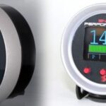
VCDS displaying diagnostic trouble codes for quick identification of sensor issues.
4.3 Can VCDS access and modify adaptation settings for interior monitoring sensors?
Yes, VCDS can access and modify adaptation settings for interior monitoring sensors. Adaptation settings are parameters that can be adjusted to customize the behavior of the sensors or the alarm system.
Some common adaptation settings for interior monitoring sensors include:
- Sensor Sensitivity: This setting adjusts the sensitivity of the sensor to movement.
- Alarm Delay: This setting adjusts the delay between when the sensor detects movement and when the alarm is triggered.
- Tilt Sensor Threshold: This setting adjusts the angle at which the tilt sensor triggers the alarm.
- Alarm Siren Volume: This setting adjusts the volume of the alarm siren.
By accessing and modifying these adaptation settings, technicians can fine-tune the interior monitoring system to meet the specific needs of the vehicle owner. However, it is important to exercise caution when modifying adaptation settings, as incorrect settings can cause the system to malfunction or trigger false alarms.
5. Benefits of Using VCDS to Read Interior Monitoring Sensor Data
Using VCDS to read interior monitoring sensor data offers several benefits for technicians and vehicle owners alike. These benefits range from improved diagnostic accuracy to enhanced security system performance.
5.1 How does VCDS improve diagnostic accuracy for interior monitoring systems?
VCDS improves diagnostic accuracy for interior monitoring systems by providing access to live data, diagnostic trouble codes (DTCs), and adaptation settings. This data allows technicians to:
- Identify Faulty Sensors: By monitoring live data, technicians can quickly identify sensors that are not functioning correctly. For example, if a sensor is not reporting any data or is reporting inaccurate data, it is likely faulty.
- Pinpoint Wiring Problems: VCDS can help technicians identify wiring problems by displaying DTCs related to circuit faults or communication errors.
- Diagnose Control Module Issues: If the control module is not communicating with the sensors or is not processing data correctly, VCDS can help technicians diagnose the issue.
- Verify Repairs: After performing repairs, technicians can use VCDS to verify that the system is functioning correctly and that all DTCs have been cleared.
By providing comprehensive diagnostic information, VCDS helps technicians diagnose issues with interior monitoring systems more accurately and efficiently.
5.2 What are the cost savings associated with using VCDS for diagnostics?
Using VCDS for diagnostics can result in significant cost savings compared to taking the vehicle to a dealership or a specialized repair shop. VCDS allows vehicle owners and independent technicians to:
- Avoid Dealership Diagnostic Fees: Dealerships typically charge high fees for diagnostic services. By using VCDS, vehicle owners can perform their own diagnostics and avoid these fees.
- Reduce Repair Costs: By accurately diagnosing the problem, technicians can avoid unnecessary repairs and replace only the faulty components.
- Save Time: VCDS can help technicians diagnose issues more quickly, reducing the amount of time spent on repairs.
- Perform Preventative Maintenance: By monitoring live data, vehicle owners can identify potential problems before they become major issues, preventing costly repairs down the road.
Overall, using VCDS for diagnostics can result in significant cost savings for vehicle owners and technicians.
5.3 How does VCDS contribute to enhanced security system performance?
VCDS contributes to enhanced security system performance by allowing technicians to:
- Optimize Sensor Sensitivity: By adjusting the sensitivity of the sensors, technicians can reduce the likelihood of false alarms while still ensuring that the system is responsive to real threats.
- Adjust Alarm Delay: By adjusting the alarm delay, technicians can prevent the alarm from being triggered by brief disturbances, such as a gust of wind or a passing vehicle.
- Customize System Settings: VCDS allows technicians to customize other system settings, such as the alarm siren volume and the tilt sensor threshold, to meet the specific needs of the vehicle owner.
- Ensure Proper Functionality: By performing diagnostic tests, technicians can ensure that all components of the security system are functioning correctly and that the system is providing adequate protection.
By optimizing and maintaining the security system using VCDS, vehicle owners can enjoy enhanced security and peace of mind.
6. Limitations of VCDS in Reading Interior Monitoring Sensor Data
While VCDS is a powerful tool for diagnosing and troubleshooting interior monitoring systems, it does have some limitations. Understanding these limitations is important for technicians to ensure they are using the tool effectively and not relying on it beyond its capabilities.
6.1 Are there vehicle models or sensor types that VCDS cannot support?
Yes, there are some vehicle models and sensor types that VCDS may not fully support. VCDS is primarily designed for Volkswagen, Audi, Skoda, and SEAT vehicles. While it may work with some other vehicle brands, its functionality may be limited.
Additionally, VCDS may not support the latest or most advanced interior monitoring sensors, especially those found in newer vehicle models. The software is constantly being updated to support new vehicles and technologies, but there may be a delay between when a new technology is introduced and when it is fully supported by VCDS.
6.2 What are the potential inaccuracies in the data provided by VCDS?
While VCDS is generally accurate, there are some potential sources of inaccuracies in the data it provides. These include:
- Software Bugs: Like any software, VCDS may contain bugs that can cause it to display inaccurate data or misinterpret sensor readings.
- Communication Errors: Communication errors between VCDS and the vehicle’s control modules can result in data corruption or incomplete data transfer.
- Sensor Calibration Issues: If the interior monitoring sensors are not properly calibrated, they may provide inaccurate readings, which will be reflected in the data displayed by VCDS.
- Hardware Limitations: The hardware used to connect VCDS to the vehicle may have limitations that can affect the accuracy of the data.
To minimize the risk of inaccuracies, it is important to use the latest version of VCDS, ensure that the sensors are properly calibrated, and use a high-quality interface cable.
6.3 When should alternative diagnostic tools be considered?
Alternative diagnostic tools should be considered in the following situations:
- When VCDS does not support the vehicle model or sensor type: If VCDS does not fully support the vehicle model or sensor type, a dealer-level diagnostic tool or an advanced aftermarket scanner may be necessary.
- When VCDS is providing inaccurate data: If VCDS is providing inaccurate data, it may be necessary to use a different diagnostic tool to verify the readings.
- When advanced diagnostic capabilities are required: Some diagnostic tasks, such as performing complex system resets or programming new control modules, may require a more advanced diagnostic tool.
- When troubleshooting non-VAG vehicles: For vehicles outside the Volkswagen Auto Group, tools designed for those specific makes and models will be more effective.
In these situations, it is important to choose a diagnostic tool that is appropriate for the specific task and vehicle.
7. Alternative Tools for Reading Interior Monitoring Sensor Data
While VCDS is a popular choice for diagnosing VAG vehicles, several alternative tools offer similar or even more advanced capabilities for reading interior monitoring sensor data. These tools range from dealer-level diagnostic systems to advanced aftermarket scanners.
7.1 What are the dealer-level diagnostic systems for VAG vehicles?
The primary dealer-level diagnostic system for Volkswagen Auto Group (VAG) vehicles is the Offboard Diagnostic Information System (ODIS). ODIS provides comprehensive diagnostic and programming capabilities for all VAG brands, including Volkswagen, Audi, Skoda, and SEAT.
ODIS offers several advantages over aftermarket diagnostic tools, including:
- Complete Vehicle Coverage: ODIS supports all VAG vehicle models, including the latest models.
- Access to Factory Data: ODIS provides access to the latest factory data, including diagnostic procedures, repair manuals, and technical service bulletins.
- Advanced Programming Capabilities: ODIS can be used to program new control modules, perform software updates, and customize vehicle settings.
- Integration with VAG Systems: ODIS is fully integrated with VAG’s online systems, allowing technicians to access real-time support and information.
However, ODIS is typically only available to authorized VAG dealerships and repair shops, and it can be expensive to purchase and maintain.
7.2 What are the popular aftermarket diagnostic scanners?
Several popular aftermarket diagnostic scanners offer similar capabilities to VCDS and ODIS. These scanners are typically more affordable and accessible than dealer-level tools, making them a popular choice for independent technicians and enthusiasts.
Some of the most popular aftermarket diagnostic scanners include:
- Autel MaxiSys Series: Autel MaxiSys scanners offer comprehensive diagnostic and programming capabilities for a wide range of vehicle brands, including VAG vehicles. They support advanced functions such as ECU coding, key programming, and active testing.
- Launch X431 Series: Launch X431 scanners are another popular choice for aftermarket diagnostics. They offer a wide range of diagnostic functions and support a variety of vehicle brands.
- Snap-on Zeus: Snap-on Zeus scanners are known for their advanced diagnostic capabilities and user-friendly interface. They offer features such as guided diagnostics, integrated repair information, and wireless connectivity.
- Thinktool Pro: Thinktool Pro scanners provide comprehensive diagnostic functions, including ECU coding, active testing, and special functions for various vehicle models.
These aftermarket scanners can be a valuable tool for diagnosing and troubleshooting interior monitoring systems, especially for technicians who work on a variety of vehicle brands.
7.3 How do these tools compare to VCDS in terms of functionality and cost?
The functionality and cost of alternative diagnostic tools vary depending on the specific model and brand. In general:
- Dealer-Level Tools (e.g., ODIS): Offer the most comprehensive functionality, including complete vehicle coverage, access to factory data, and advanced programming capabilities. However, they are typically the most expensive and are only available to authorized dealerships and repair shops.
- Advanced Aftermarket Scanners (e.g., Autel MaxiSys, Launch X431, Snap-on Zeus): Offer a wide range of diagnostic and programming capabilities for a variety of vehicle brands. They are typically more affordable than dealer-level tools but more expensive than VCDS.
- VCDS: Offers excellent functionality for VAG vehicles at an affordable price. It may not support as many advanced functions as dealer-level tools or advanced aftermarket scanners, but it provides a good balance between functionality and cost for VAG vehicle diagnostics.
- Thinktool Pro: Provide comprehensive diagnostic functions, including ECU coding, active testing, and special functions for various vehicle models
Ultimately, the best diagnostic tool depends on the specific needs and budget of the technician or vehicle owner.
8. Step-by-Step Guide: Reading Interior Monitoring Sensor Data with VCDS
This section provides a step-by-step guide on how to use VCDS to read data from interior monitoring sensors. Follow these steps to accurately diagnose and troubleshoot issues related to your vehicle’s security system.
8.1 Connecting VCDS to the vehicle
- Locate the Diagnostic Port: The diagnostic port (also known as the OBD-II port) is typically located under the dashboard on the driver’s side of the vehicle.
- Connect the VCDS Interface Cable: Plug one end of the VCDS interface cable into the diagnostic port and the other end into your computer’s USB port.
- Turn on the Ignition: Turn the vehicle’s ignition to the “on” position, but do not start the engine.
- Launch VCDS: Open the VCDS software on your computer.
- Test the Connection: Click on the “Options” button in VCDS and select the correct COM port for your interface cable. Then, click on the “Test” button to verify that VCDS can communicate with the vehicle.
Connecting VCDS to the diagnostic port for accessing vehicle data.
8.2 Accessing the interior monitoring system control module
- Select Control Module: In the VCDS main menu, click on the “Select” button to access the control module selection screen.
- Identify the Correct Module: Locate the control module responsible for the interior monitoring system. This may be labeled as “Central Convenience,” “Alarm System,” or something similar. Refer to your vehicle’s service manual for the exact name and address of the module.
- Select the Module: Click on the module to select it. VCDS will then establish a connection with the module.
8.3 Reading live data and diagnostic trouble codes (DTCs)
- Access Live Data: Once you have selected the control module, click on the “Measuring Blocks” button to access live data.
- Select Parameters: Choose the live data parameters that you want to monitor, such as sensor status, signal strength, and voltage.
- View Live Data: VCDS will display the selected parameters in real-time. Monitor the data to identify any anomalies or out-of-range values.
- Read Diagnostic Trouble Codes (DTCs): Click on the “Fault Codes” button to read any diagnostic trouble codes (DTCs) stored in the control module’s memory.
- Interpret DTCs: VCDS will display the DTCs along with a brief description of each fault. Refer to your vehicle’s service manual or online resources for more information about the DTCs and their possible causes.
- Clear DTCs (Optional): After repairing the fault, you can click on the “Clear Codes” button to erase the DTCs from the control module’s memory.
By following these steps, you can use VCDS to read live data and diagnostic trouble codes (DTCs) from interior monitoring sensors, allowing you to diagnose and troubleshoot issues with your vehicle’s security system.
9. Advanced VCDS Techniques for Interior Monitoring System Diagnostics
Beyond the basics, VCDS offers several advanced techniques that can further enhance your diagnostic capabilities for interior monitoring systems. These techniques allow for more in-depth analysis and troubleshooting of complex issues.
9.1 Using adaptation settings to troubleshoot sensor issues
Adaptation settings in VCDS allow you to modify the behavior of the interior monitoring sensors and the alarm system. By carefully adjusting these settings, you can troubleshoot sensor issues and optimize system performance.
Some examples of how adaptation settings can be used for troubleshooting include:
- Adjusting Sensor Sensitivity: If a sensor is triggering false alarms, you can reduce its sensitivity to prevent it from being triggered by minor disturbances.
- Changing Alarm Delay: If the alarm is being triggered too quickly, you can increase the alarm delay to give the system more time to verify the threat.
- Disabling Sensors: If a sensor is malfunctioning and causing problems, you can temporarily disable it to prevent it from triggering the alarm.
To access adaptation settings in VCDS, click on the “Adaptation” button in the control module screen. Then, select the channel that you want to modify and enter the new value. Be sure to record the original value before making any changes, so that you can revert to the original settings if necessary.
9.2 Performing output tests to verify sensor functionality
Output tests in VCDS allow you to directly activate various components of the interior monitoring system, such as the alarm siren and the indicator lights. By performing these tests, you can verify that the components are functioning correctly and that the wiring is intact.
To perform output tests in VCDS, click on the “Output Tests” button in the control module screen. Then, select the component that you want to test and click on the “Start” button. VCDS will activate the component for a specified period of time.
Listen for the alarm siren to sound and watch for the indicator lights to flash. If any of the components do not respond as expected, there may be a problem with the component itself or with the wiring.
9.3 Analyzing data logs to identify intermittent problems
Data logging in VCDS allows you to record live data over a period of time. This can be useful for identifying intermittent problems that may not be apparent during a static diagnostic test.
To create a data log in VCDS, click on the “Data Logging” button in the main menu. Then, select the control module and the live data parameters that you want to record. Click on the “Start” button to begin recording data.
Drive the vehicle under the conditions that typically trigger the intermittent problem. After the problem has occurred, stop the data log and save the file.
Open the data log file in a spreadsheet program, such as Microsoft Excel, and analyze the data. Look for any spikes, drops, or other anomalies that may indicate a problem with the sensors or the control module.
By analyzing data logs, you can gain valuable insights into intermittent problems and identify the root cause of the issue.
10. Troubleshooting Common Issues When Reading Interior Monitoring Sensor Data
Even with a powerful tool like VCDS, you may encounter issues when reading data from interior monitoring sensors. This section outlines some common problems and provides troubleshooting tips to help you resolve them.
10.1 VCDS cannot connect to the control module
If VCDS cannot connect to the control module, there may be a problem with the connection between VCDS and the vehicle. Here are some troubleshooting steps to try:
- Verify the Connection: Make sure that the VCDS interface cable is securely plugged into the diagnostic port and the computer’s USB port.
- Check the Ignition: Ensure that the vehicle’s ignition is turned to the “on” position, but do not start the engine.
- Test the COM Port: In the VCDS options, verify that the correct COM port is selected for your interface cable. Click on the “Test” button to confirm that VCDS can communicate with the vehicle.
- Check the Cable: Try using a different VCDS interface cable to rule out a faulty cable.
- Check the Vehicle’s Battery: A weak or failing battery can sometimes prevent VCDS from connecting to the control module. Try jump-starting the vehicle or connecting a battery charger.
- Check for Damaged Wiring: Inspect the wiring and connectors around the diagnostic port and the control module for any signs of damage or corrosion.
- Update VCDS: Make sure you are using the latest version of VCDS.
If you have tried all of these troubleshooting steps and VCDS still cannot connect to the control module, there may be a problem with the control module itself.
10.2 Inaccurate or inconsistent sensor readings
If VCDS is displaying inaccurate or inconsistent sensor readings, there may be a problem with the sensors themselves or with the wiring. Here are some troubleshooting steps to try:
- Check Sensor Calibration: Verify that the sensors are properly calibrated. Refer to your vehicle’s service manual for the correct calibration procedure.
- Inspect Wiring: Inspect the wiring and connectors around the sensors for any signs of damage or corrosion.
- Test Sensor Voltage: Use a multimeter to measure the voltage supplied to the sensors. Ensure that the voltage is within the specified range.
- Check for Interference: Make sure that there are no sources of electromagnetic interference (EMI) near the sensors. EMI can cause inaccurate sensor readings.
- Replace Sensors: If you suspect that a sensor is faulty, try replacing it with a new sensor.
10.3 False alarms and system malfunctions
False alarms and system malfunctions can be caused by a variety of factors, including faulty sensors, wiring problems, and incorrect adaptation settings. Here are some troubleshooting steps to try:
- Check for Loose Objects: Make sure that there are no loose objects moving around inside the vehicle, as this can trigger the sensors.
- Adjust Sensor Sensitivity: Reduce the sensitivity of the sensors to prevent them from being triggered by minor disturbances.
- Check Door and Hood Sensors: Ensure that the door and hood sensors are functioning correctly and that the doors and hood are properly closed and secured.
- Inspect Wiring: Inspect the wiring and connectors around the sensors and the control module for any signs of damage or corrosion.
- Check Battery: A weak or failing battery can cause the alarm system to malfunction or trigger false alarms. Test or replace the battery.
- Reset the System: Try resetting the alarm system by disconnecting the battery for a few minutes and then reconnecting it.
If you are still experiencing false alarms or system malfunctions after trying these troubleshooting steps, there may be a problem with the control module itself.
11. Optimizing VCDS for Enhanced Interior Monitoring System Performance
To get the most out of VCDS and ensure accurate diagnostics, it’s essential to optimize the software and your workflow. This section provides tips on how to configure VCDS for enhanced interior monitoring system performance.
11.1 Updating VCDS software and firmware
Keeping your VCDS software and firmware up to date is crucial for ensuring compatibility with the latest vehicle models and sensor types, as well as for fixing bugs and improving performance.
To update VCDS software:
- Check for Updates: Open the VCDS software and click on the “Options” button.
- Click on “Check for Updates”: If an update is available, follow the on-screen instructions to download and install it.
To update VCDS firmware:
- Connect VCDS to the Vehicle: Connect the VCDS interface cable to the vehicle’s diagnostic port and your computer.
- Open VCDS: Open the VCDS software and click on the “Options” button.
- Click on “Update Firmware”: If a firmware update is available, follow the on-screen instructions to update the firmware.
It is important to follow the instructions carefully when updating VCDS software and firmware, as an interrupted update can cause the software or interface cable to malfunction.
11.2 Configuring VCDS settings for optimal performance
Configuring VCDS settings for optimal performance can help improve the accuracy and speed of diagnostics. Here are some settings to consider:
- COM Port: Select the correct COM port for your interface cable.
- Latency Timer: Adjust the latency timer to optimize communication speed. A lower latency timer may improve performance, but it can also increase the risk of communication errors.
- KWP2000 Slow Init: Enable this option if you are having trouble connecting to older vehicles.
- Clear DTCs After Read: Enable this option to automatically clear DTCs after reading them.
- Auto-Scan Options: Customize the auto-scan options to include only the control modules that you are interested in.
Experiment with these settings to find the configuration that works best for your vehicle and diagnostic tasks.
11.3 Creating custom data logging profiles for specific diagnostics
Creating custom data logging profiles can save time and improve the efficiency of diagnostics by allowing you to quickly record the live data parameters that are most relevant to a specific problem.
To create a custom data logging profile:
- Open VCDS: Open the VCDS software and click on the “Data Logging” button in the main menu.
- Select Control Module: Select the control module that you want to log data from.
- Select Parameters: Choose the live data parameters that you want to record.
- Save Profile: Click on the “Save Profile” button and enter a name for your profile.
Once you have created a custom data logging profile, you can quickly load it by clicking on the “Load Profile” button and selecting the profile from the list.
By creating custom data logging profiles, you can streamline your diagnostic workflow and focus on the data that is most important for identifying the problem.
12. Expert Tips for Accurate Interior Monitoring Sensor Diagnosis with VCDS
Accurate diagnosis of interior monitoring sensor issues requires a combination of technical knowledge, diagnostic skills, and attention to detail. Here are some expert tips to help you diagnose these issues accurately with VCDS:
12.1 Understanding vehicle-specific wiring diagrams
Understanding vehicle-specific wiring diagrams is crucial for troubleshooting electrical issues in the interior monitoring system. Wiring diagrams provide detailed information about the wiring harnesses, connectors, and components in the system.
By studying the wiring diagrams, you can:
- Identify Wiring Routes: Trace the wiring routes to locate damaged or corroded wires.
- Locate Connectors: Find the locations of connectors to inspect them for corrosion or loose connections.
- Identify Components: Identify the locations of components, such as sensors and control modules, to test them or replace them.
- Understand System Operation: Gain a better understanding of how the system works and how the components interact with each other.
Vehicle-specific wiring diagrams are typically available in the vehicle’s service manual or online databases.
12.2 Using a multimeter to verify sensor signals and power supply
A multimeter is an essential tool for verifying sensor signals and power supply. By using a multimeter, you can:
- Measure Voltage: Check the voltage supplied to the sensors and the control module.
- Measure Resistance: Check the resistance of the wiring and the sensors to identify short circuits or open circuits.
- Measure Continuity: Check the continuity of the wiring to ensure that there are no breaks in the circuit.
- Measure Signal Strength: Measure the strength of the signals emitted by the sensors.
Refer to your vehicle’s service manual for the correct voltage, resistance, and signal strength values for each component.
12.3 Documenting diagnostic steps and findings
Documenting diagnostic steps and findings is important for tracking your progress, avoiding mistakes, and communicating your findings to others.
When diagnosing interior monitoring sensor issues, be sure to:
- Record DTCs: Write down all of the DTCs that you