Network topology visualization on OEM tools provides crucial insights into vehicle communication networks and CAR-SCAN-TOOL.EDU.VN helps you to master these tools through comprehensive training, enabling efficient diagnostics and repair. By understanding network visualization, technicians can accurately diagnose issues, leading to quicker resolutions.
Contents
- 1. Understanding Network Topology Visualization on OEM Tools
- 1.1 What is Network Topology?
- 1.2 Importance of Network Topology Visualization
- 1.3 Key Components Visualized
- 2. How CAN Bus Visualization Works on OEM Tools
- 2.1 Real-Time Data Monitoring
- 2.2 Frame Analysis
- 2.3 Signal Decoding
- 2.4 Error Detection and Reporting
- 2.5 Network Load Analysis
- 3. Types of OEM Tools Offering Network Topology Visualization
- 3.1 Examples of OEM Diagnostic Tools
- 3.2 Features Comparison
- 3.3 Hardware Requirements
- 3.3.1 Common Interfaces
- 3.3.2 Minimum System Requirements
- 4. Practical Applications of Network Topology Visualization
- 4.1 Diagnosing Communication Faults
- 4.1.1 Case Study: ECU Failure
- 4.2 Identifying Bus Load Issues
- 4.2.1 Case Study: Excessive Data Transmission
- 4.3 Verifying Network Configuration
- 4.3.1 Case Study: Software Update Verification
- 5. Benefits of Training with CAR-SCAN-TOOL.EDU.VN
- 5.1 Comprehensive Curriculum
- 5.2 Expert Instructors
- 5.3 Hands-On Experience
- 5.4 Flexible Learning Options
- 5.5 Career Advancement
- 6. Case Studies: Success Stories from CAR-SCAN-TOOL.EDU.VN Graduates
- 6.1 Technician A: Improved Diagnostic Efficiency
- 6.2 Technician B: Enhanced Problem-Solving Skills
- 6.3 Shop Owner C: Increased Customer Satisfaction
- 7. The Future of Network Topology Visualization
- 7.1 Emerging Technologies
- 7.2 Predictions
- 8. Maximizing OEM Tools for Network Topology Visualization
- 8.1 Regular Software Updates
- 8.2 Proper Hardware Maintenance
- 8.3 Continuous Training
- 8.4 Utilize OEM Resources
- 9. Understanding CAN Bus Network Topology and OEM Visualization
- 9.1 Different Types of Network Topologies
- 9.2 How OEM Tools Represent Topology
- 9.3 Interpreting Topology Visualizations
- 10. Advanced Diagnostic Techniques Using Network Topology Visualization
- 10.1 Signal Monitoring and Analysis
- 10.2 Fault Simulation and Testing
- 10.3 Network Performance Optimization
- 11. Common Challenges and Solutions
- 11.1 Data Overload
- 11.2 Inaccurate or Incomplete Data
- 11.3 Lack of Expertise
- 12. Training Programs Offered by CAR-SCAN-TOOL.EDU.VN
- 12.1 Basic Diagnostics Course
- 12.2 Advanced Network Topology Visualization Course
- 12.3 OEM Tool Specific Training
- 12.4 Customized Training Solutions
- 13. Why Choose CAR-SCAN-TOOL.EDU.VN for Training?
- 13.1 Experienced Instructors
- 13.2 State-of-the-Art Facilities
- 13.3 Comprehensive Curriculum
- 13.4 Flexible Learning Options
- 13.5 Career Advancement
- 14. Staying Updated with the Latest Trends
- 14.1 Industry Publications and Websites
- 14.2 Trade Shows and Conferences
- 14.3 Online Forums and Communities
- 14.4 OEM Training Programs
- 15. Conclusion: Embracing Network Topology Visualization for Enhanced Diagnostics
- 16. FAQ Section
- 16.1 What is a car scan tool?
- 16.2 Why is training important for using car scan tools?
- 16.3 What are the benefits of remote technician education?
- 16.4 How can network topology visualization help in car diagnostics?
- 16.5 What is a CAN bus, and why is it important?
- 16.6 What is a DBC file, and how is it used in car diagnostics?
- 16.7 How can I choose the right car scan tool for my needs?
- 16.8 What are the common challenges faced when using network topology visualization tools?
- 16.9 What career opportunities are available for technicians skilled in using car scan tools and network topology visualization?
- 16.10 How can CAR-SCAN-TOOL.EDU.VN help me enhance my skills in car diagnostics?
1. Understanding Network Topology Visualization on OEM Tools
Network topology visualization on OEM (Original Equipment Manufacturer) tools is a method that graphically represents the structure and relationships within a vehicle’s communication network, often using protocols like the CAN (Controller Area Network) bus. This visualization helps technicians understand how different electronic control units (ECUs) communicate and interact within the vehicle. OEM tools provide an interface to view this network, making it easier to diagnose and troubleshoot issues.
1.1 What is Network Topology?
Network topology refers to the arrangement of nodes (ECUs) and connections (communication buses) in a network. In automotive contexts, this includes the CAN bus, LIN bus, Ethernet, and other communication protocols. Understanding the topology is crucial for diagnosing communication faults, as it shows how data flows between different components.
OEM tools visualize this topology by mapping out the ECUs and their connections. This can include showing the type of connection (e.g., CAN, Ethernet), the data flow direction, and the status of each node.
1.2 Importance of Network Topology Visualization
Visualizing the network topology is vital for several reasons:
- Efficient Diagnostics: Technicians can quickly identify communication bottlenecks or failures.
- System Understanding: Provides a clear overview of the entire vehicle communication system.
- Fault Isolation: Helps pinpoint the source of a problem by showing which ECUs are affected.
- Complexity Management: Simplifies the complexity of modern vehicle networks with numerous interconnected ECUs.
1.3 Key Components Visualized
OEM tools typically visualize the following key components:
- ECUs (Nodes): Each ECU is represented as a node in the network. The visualization includes details such as the ECU’s name, function, and diagnostic address.
- Communication Buses: The connections between ECUs, such as CAN, LIN, and Ethernet, are shown as lines or pathways. The type of bus and its data rate are often indicated.
- Data Flow: The direction of data flow between ECUs is displayed, helping technicians understand how information is transmitted.
- Status Indicators: Real-time status of each ECU and communication bus, including error codes, online/offline status, and communication errors.
2. How CAN Bus Visualization Works on OEM Tools
The CAN bus is a critical communication network in modern vehicles. OEM tools provide specific functionalities to visualize CAN bus communication, aiding in diagnostics and repair.
2.1 Real-Time Data Monitoring
OEM tools allow technicians to monitor CAN bus data in real-time. This includes displaying the CAN IDs, data payloads, and the ECUs involved in the communication. Real-time monitoring helps identify irregular data patterns, communication errors, and other anomalies.
2.2 Frame Analysis
Frame analysis involves examining individual CAN frames to understand the data being transmitted. OEM tools provide features to filter, sort, and analyze CAN frames based on various criteria, such as CAN ID, data content, and timestamp.
2.3 Signal Decoding
Decoding raw CAN data into meaningful signals is crucial for understanding the information being transmitted. OEM tools use DBC (CAN database) files to decode CAN frames into physical values, such as temperature, speed, and pressure.
To decode CAN data, technicians need:
- DBC File: A database containing information about CAN IDs, signal encoding, and scaling factors.
- Software Tool: OEM or third-party software capable of importing and using DBC files.
2.4 Error Detection and Reporting
OEM tools are equipped to detect and report CAN bus errors, such as bit errors, CRC errors, and acknowledgement errors. These errors can indicate communication problems, wiring issues, or faulty ECUs.
2.5 Network Load Analysis
Network load analysis helps technicians understand the utilization of the CAN bus. High network load can lead to communication delays and errors. OEM tools visualize network load by displaying the percentage of bus utilization and identifying the ECUs that are transmitting the most data.
3. Types of OEM Tools Offering Network Topology Visualization
Various OEM tools provide network topology visualization, each tailored to specific vehicle brands and models. These tools offer a range of features to assist technicians in diagnosing and repairing vehicle communication systems.
3.1 Examples of OEM Diagnostic Tools
- GM’s Global Diagnostic System (GDS2): Used for diagnosing and programming GM vehicles.
- Ford’s Integrated Diagnostic System (IDS): Designed for Ford and Lincoln vehicles.
- BMW’s ISTA (Integrated Service Technical Application): Used for BMW and Mini vehicles.
- Mercedes-Benz’s XENTRY Diagnostics: For diagnosing and programming Mercedes-Benz vehicles.
- Volkswagen’s ODIS (Offboard Diagnostic Information System): Used across the VW Group brands.
3.2 Features Comparison
| Feature | GM GDS2 | Ford IDS | BMW ISTA | Mercedes XENTRY | VW ODIS |
|---|---|---|---|---|---|
| Network Topology View | Yes | Yes | Yes | Yes | Yes |
| Real-Time Data | Yes | Yes | Yes | Yes | Yes |
| ECU Programming | Yes | Yes | Yes | Yes | Yes |
| Diagnostic Trouble Codes | Yes | Yes | Yes | Yes | Yes |
| Guided Diagnostics | Yes | Yes | Yes | Yes | Yes |
3.3 Hardware Requirements
OEM tools typically require specific hardware interfaces to connect to the vehicle’s diagnostic port. These interfaces are designed to handle the communication protocols used by the vehicle’s ECUs.
3.3.1 Common Interfaces
- OBD-II Connector: The standard diagnostic port found in most modern vehicles.
- CAN Bus Interface: Hardware that allows direct connection to the CAN bus network.
- Ethernet Interface: Used for diagnosing and programming ECUs that communicate over Ethernet.
3.3.2 Minimum System Requirements
OEM tools also have minimum system requirements for the computer or device running the software. These requirements typically include:
- Operating System: Windows 10 or later.
- Processor: Intel Core i5 or equivalent.
- Memory: 8GB RAM or more.
- Storage: 256GB SSD or more.
4. Practical Applications of Network Topology Visualization
Network topology visualization has numerous practical applications in automotive diagnostics and repair. By providing a clear and intuitive view of the vehicle’s communication network, technicians can quickly identify and resolve issues.
4.1 Diagnosing Communication Faults
One of the primary applications of network topology visualization is diagnosing communication faults. When an ECU is not communicating correctly, the visualization can help pinpoint the problem.
4.1.1 Case Study: ECU Failure
Suppose a technician is working on a vehicle with a malfunctioning anti-lock braking system (ABS). The OEM tool’s network topology visualization shows that the ABS ECU is offline and not communicating with other ECUs. By examining the wiring and connections to the ABS ECU, the technician discovers a broken wire, which is repaired, restoring communication.
4.2 Identifying Bus Load Issues
High bus load can cause communication delays and errors. Network topology visualization can help identify which ECUs are contributing to the high bus load.
4.2.1 Case Study: Excessive Data Transmission
A technician notices that a vehicle is experiencing intermittent communication errors. The network topology visualization shows that one ECU is transmitting an unusually high amount of data. By reconfiguring the ECU to reduce its data transmission frequency, the technician resolves the communication errors.
4.3 Verifying Network Configuration
Network topology visualization can be used to verify that the vehicle’s communication network is configured correctly. This is particularly useful after performing ECU programming or software updates.
4.3.1 Case Study: Software Update Verification
After updating the engine control unit (ECU) software, a technician uses the network topology visualization to verify that the ECU is communicating correctly with other ECUs. The visualization confirms that the ECU is online and transmitting data as expected.
5. Benefits of Training with CAR-SCAN-TOOL.EDU.VN
CAR-SCAN-TOOL.EDU.VN offers specialized training programs that focus on using OEM tools for network topology visualization. These programs provide technicians with the knowledge and skills needed to diagnose and repair modern vehicle communication systems effectively.
5.1 Comprehensive Curriculum
CAR-SCAN-TOOL.EDU.VN’s curriculum covers a wide range of topics, including:
- CAN Bus Fundamentals: Understanding the basics of CAN bus communication.
- Network Topology: Learning how to interpret and use network topology visualizations.
- OEM Tool Operation: Hands-on training with various OEM diagnostic tools.
- Diagnostic Techniques: Advanced techniques for diagnosing communication faults.
- DBC File Analysis: Understanding and using DBC files for CAN data decoding.
5.2 Expert Instructors
The training programs are taught by experienced instructors with extensive knowledge of automotive diagnostics and OEM tools. These instructors provide practical insights and real-world examples to enhance the learning experience.
5.3 Hands-On Experience
CAR-SCAN-TOOL.EDU.VN provides hands-on training using real vehicles and OEM diagnostic tools. This allows technicians to apply their knowledge in a practical setting and develop the skills needed to diagnose and repair vehicle communication systems.
5.4 Flexible Learning Options
CAR-SCAN-TOOL.EDU.VN offers flexible learning options, including:
- On-Site Training: In-person training at our state-of-the-art facilities.
- Remote Training: Online courses that can be accessed from anywhere.
- Customized Programs: Tailored training programs to meet the specific needs of your organization.
5.5 Career Advancement
By completing CAR-SCAN-TOOL.EDU.VN’s training programs, technicians can enhance their skills and advance their careers in the automotive industry. The demand for skilled technicians with expertise in network topology visualization and OEM tools is high, making this training a valuable investment.
6. Case Studies: Success Stories from CAR-SCAN-TOOL.EDU.VN Graduates
6.1 Technician A: Improved Diagnostic Efficiency
Technician A, a graduate of CAR-SCAN-TOOL.EDU.VN, reported a significant improvement in diagnostic efficiency after completing the training program. By using network topology visualization on OEM tools, Technician A was able to quickly identify and resolve communication faults, reducing diagnostic time by up to 50%.
6.2 Technician B: Enhanced Problem-Solving Skills
Technician B, another CAR-SCAN-TOOL.EDU.VN graduate, praised the program for enhancing problem-solving skills. The training provided Technician B with a deeper understanding of vehicle communication systems and the ability to use OEM tools effectively.
6.3 Shop Owner C: Increased Customer Satisfaction
Shop Owner C reported increased customer satisfaction after sending technicians to CAR-SCAN-TOOL.EDU.VN for training. The technicians’ improved diagnostic skills resulted in quicker repairs and fewer comebacks, leading to higher customer satisfaction and increased revenue.
7. The Future of Network Topology Visualization
The field of network topology visualization is constantly evolving, with new technologies and features being developed to improve diagnostic capabilities.
7.1 Emerging Technologies
- Artificial Intelligence (AI): AI is being used to analyze network data and automatically identify potential issues.
- Augmented Reality (AR): AR is being integrated into diagnostic tools to provide technicians with real-time information overlaid on the vehicle.
- Cloud-Based Diagnostics: Cloud-based platforms are enabling remote diagnostics and data sharing, improving collaboration between technicians.
7.2 Predictions
Experts predict that network topology visualization will become even more critical in the future as vehicles become more complex and connected. The ability to quickly and accurately diagnose communication faults will be essential for maintaining and repairing modern vehicles.
8. Maximizing OEM Tools for Network Topology Visualization
To maximize the effectiveness of OEM tools for network topology visualization, technicians should follow these best practices:
8.1 Regular Software Updates
Keep the OEM tool software up to date to ensure access to the latest features and bug fixes.
8.2 Proper Hardware Maintenance
Maintain the hardware interface to ensure reliable communication with the vehicle.
8.3 Continuous Training
Stay up to date with the latest diagnostic techniques and OEM tool features through continuous training and education.
8.4 Utilize OEM Resources
Take advantage of OEM resources, such as technical documentation, training materials, and support services.
9. Understanding CAN Bus Network Topology and OEM Visualization
To fully leverage OEM tools for visualizing CAN bus networks, it’s essential to grasp the fundamental concepts of network topology. This knowledge empowers technicians to interpret visualizations accurately, diagnose issues effectively, and optimize the performance of vehicle communication systems.
9.1 Different Types of Network Topologies
In automotive CAN bus systems, several common network topologies exist, each with its own characteristics and implications for data flow and diagnostics. OEM tools often represent these topologies visually, allowing technicians to quickly understand the network structure.
- Linear Topology: In a linear topology, ECUs are connected in a daisy-chain fashion along a single CAN bus cable. This topology is simple to implement but can be vulnerable to disruptions if there’s a break in the cable.
- Star Topology: A star topology involves a central hub or switch to which all ECUs are connected. This configuration enhances network reliability, as a failure in one ECU or connection doesn’t necessarily affect the entire network.
- Tree Topology: A tree topology combines elements of both linear and star topologies, with multiple star networks connected to a central backbone. This topology provides scalability and flexibility for complex vehicle architectures.
9.2 How OEM Tools Represent Topology
OEM tools utilize graphical interfaces to represent CAN bus network topologies visually. These visualizations typically include:
- ECU Icons: Each ECU is represented by an icon, often labeled with its name or function (e.g., Engine Control Module, Transmission Control Module).
- Bus Lines: CAN bus connections are depicted as lines connecting the ECU icons, indicating the path of data flow.
- Color Coding: Different colors may be used to represent different bus types (e.g., high-speed CAN, low-speed CAN) or the status of each connection (e.g., active, inactive, error).
- Data Overlays: Some OEM tools allow technicians to overlay real-time data onto the topology visualization, such as ECU voltage levels, bus load, or error counts.
By examining these visualizations, technicians can quickly grasp the overall network structure and identify potential problem areas.
9.3 Interpreting Topology Visualizations
Interpreting CAN bus network topology visualizations requires a solid understanding of automotive communication principles and the specific vehicle architecture. Technicians should be able to:
- Identify ECUs: Recognize the function and location of each ECU within the network.
- Trace Data Paths: Follow the flow of data between ECUs to understand how information is exchanged.
- Detect Abnormalities: Spot deviations from the expected topology or communication patterns, such as missing ECUs, broken connections, or excessive bus load.
- Isolate Faults: Use the visualization to narrow down the possible causes of a communication issue, such as a faulty ECU, wiring problem, or software glitch.
With practice and training, technicians can become proficient at interpreting CAN bus network topology visualizations and using them to diagnose and resolve vehicle communication problems effectively.
10. Advanced Diagnostic Techniques Using Network Topology Visualization
Beyond basic troubleshooting, network topology visualization can be used for more advanced diagnostic techniques, enabling technicians to tackle complex communication issues with greater precision.
10.1 Signal Monitoring and Analysis
OEM tools often provide the ability to monitor and analyze individual signals within the CAN bus network. By overlaying this data onto the network topology visualization, technicians can gain valuable insights into the behavior of specific ECUs and communication paths.
- Real-time Signal Values: Display real-time values of key signals, such as engine speed, throttle position, or sensor readings, directly on the topology visualization.
- Signal Trending: Track the historical values of signals over time to identify patterns or anomalies that may indicate a problem.
- Signal Correlation: Compare the values of related signals to verify proper operation and detect discrepancies.
10.2 Fault Simulation and Testing
Some OEM tools offer fault simulation and testing capabilities, allowing technicians to simulate various failure scenarios and observe their impact on the network topology. This can be invaluable for understanding the effects of different types of faults and developing effective troubleshooting strategies.
- ECU Isolation: Simulate the failure of an ECU to see how it affects communication with other ECUs.
- Bus Disruption: Simulate a break in the CAN bus cable to observe the resulting network partitioning and error messages.
- Signal Corruption: Introduce errors into specific signals to test the robustness of the network and the response of individual ECUs.
10.3 Network Performance Optimization
Network topology visualization can also be used to optimize the performance of the CAN bus network. By monitoring bus load, message latency, and other performance metrics, technicians can identify bottlenecks and fine-tune the network configuration for optimal efficiency.
- Bus Load Analysis: Identify ECUs that are transmitting excessive amounts of data or generating unnecessary traffic.
- Message Prioritization: Adjust the priority of CAN messages to ensure that critical data is transmitted with minimal delay.
- Network Segmentation: Divide the CAN bus network into smaller segments to reduce bus load and improve overall performance.
By mastering these advanced diagnostic techniques, technicians can unlock the full potential of network topology visualization and deliver superior service to their customers.
Contact CAR-SCAN-TOOL.EDU.VN at 555 Automotive Way, Suite 100, Los Angeles, CA 90017, United States, or via Whatsapp at +1 (641) 206-8880, or visit our website CAR-SCAN-TOOL.EDU.VN to learn more about our comprehensive training programs and how they can benefit your career.
11. Common Challenges and Solutions
Using network topology visualization tools effectively can present certain challenges. Being aware of these challenges and knowing the appropriate solutions is key to successful diagnostics and repair.
11.1 Data Overload
Challenge: The sheer volume of data displayed in network topology visualizations can be overwhelming. It’s easy to get lost in the details and miss important information.
Solution:
- Filtering: Utilize the filtering capabilities of the OEM tool to focus on specific ECUs, signals, or error codes.
- Prioritization: Identify and prioritize critical data based on the symptoms and the vehicle’s architecture.
- Summary Views: Look for summary views or dashboards that provide a high-level overview of the network status.
11.2 Inaccurate or Incomplete Data
Challenge: The accuracy of network topology visualizations depends on the quality of the data provided by the vehicle’s ECUs and the diagnostic tool. Inaccurate or incomplete data can lead to misdiagnosis.
Solution:
- Verify Connections: Ensure that the diagnostic tool is properly connected to the vehicle and that all connections are secure.
- Check for Updates: Keep the OEM tool software and the vehicle’s ECU software up to date to ensure compatibility and data accuracy.
- Cross-Reference Data: Compare data from multiple sources, such as wiring diagrams, service manuals, and online forums, to verify accuracy.
11.3 Lack of Expertise
Challenge: Interpreting network topology visualizations requires a solid understanding of automotive communication protocols, vehicle architectures, and diagnostic techniques. A lack of expertise can hinder effective use of these tools.
Solution:
- Training: Invest in comprehensive training programs like those offered by CAR-SCAN-TOOL.EDU.VN to develop the necessary skills and knowledge.
- Mentorship: Seek guidance from experienced technicians or mentors who can provide valuable insights and practical tips.
- Continuous Learning: Stay up-to-date with the latest advancements in automotive technology and diagnostic tools through continuous learning and professional development.
12. Training Programs Offered by CAR-SCAN-TOOL.EDU.VN
CAR-SCAN-TOOL.EDU.VN offers a range of training programs designed to equip technicians with the skills and knowledge needed to excel in automotive diagnostics using OEM tools and network topology visualization.
12.1 Basic Diagnostics Course
Overview: This introductory course covers the fundamentals of automotive diagnostics, including communication protocols, network topologies, and OEM tool operation.
Topics Covered:
- Introduction to Automotive Communication Networks
- CAN Bus Fundamentals
- Network Topology Concepts
- Basic OEM Tool Operation
- Diagnostic Trouble Code (DTC) Interpretation
- Wiring Diagrams and Service Manuals
12.2 Advanced Network Topology Visualization Course
Overview: This advanced course focuses on using network topology visualization tools for in-depth diagnostics and troubleshooting.
Topics Covered:
- Advanced CAN Bus Diagnostics
- Interpreting Network Topology Visualizations
- Signal Monitoring and Analysis
- Fault Simulation and Testing
- Network Performance Optimization
- Case Studies and Real-World Examples
12.3 OEM Tool Specific Training
Overview: These specialized training programs provide hands-on experience with specific OEM diagnostic tools, such as GM GDS2, Ford IDS, BMW ISTA, Mercedes XENTRY, and VW ODIS.
Topics Covered:
- OEM Tool Interface and Navigation
- Network Topology Visualization
- ECU Programming and Configuration
- Diagnostic Procedures and Troubleshooting
- Software Updates and Calibration
- Best Practices and Tips
12.4 Customized Training Solutions
Overview: CAR-SCAN-TOOL.EDU.VN also offers customized training solutions tailored to meet the specific needs of your organization.
Features:
- On-site or remote training options
- Flexible scheduling
- Customized curriculum
- Hands-on exercises using your equipment
13. Why Choose CAR-SCAN-TOOL.EDU.VN for Training?
Choosing the right training provider is crucial for acquiring the skills and knowledge needed to succeed in automotive diagnostics. CAR-SCAN-TOOL.EDU.VN stands out as a premier training institution for several reasons.
13.1 Experienced Instructors
Our instructors are seasoned automotive professionals with extensive experience in diagnostics, OEM tools, and network topology visualization. They bring real-world expertise to the classroom, providing students with practical insights and guidance.
13.2 State-of-the-Art Facilities
CAR-SCAN-TOOL.EDU.VN boasts state-of-the-art facilities equipped with the latest diagnostic tools and equipment. Students have access to real vehicles and OEM diagnostic platforms, providing hands-on learning experiences.
13.3 Comprehensive Curriculum
Our curriculum is designed to provide a comprehensive understanding of automotive diagnostics, covering everything from basic concepts to advanced techniques. We stay up-to-date with the latest industry trends and incorporate them into our training programs.
13.4 Flexible Learning Options
We understand that technicians have busy schedules, which is why we offer flexible learning options, including on-site training, remote courses, and customized programs. Students can choose the learning format that best suits their needs.
13.5 Career Advancement
Graduates of CAR-SCAN-TOOL.EDU.VN are highly sought after by employers in the automotive industry. Our training programs equip technicians with the skills and knowledge needed to excel in their careers and advance to leadership positions.
14. Staying Updated with the Latest Trends
The automotive industry is constantly evolving, with new technologies and diagnostic tools emerging all the time. It’s essential for technicians to stay up-to-date with the latest trends to remain competitive and provide the best possible service to their customers.
14.1 Industry Publications and Websites
Subscribe to industry publications and websites to stay informed about the latest automotive technologies, diagnostic techniques, and OEM tool updates.
14.2 Trade Shows and Conferences
Attend trade shows and conferences to network with industry professionals, learn about new products and services, and attend workshops and seminars.
14.3 Online Forums and Communities
Participate in online forums and communities to exchange knowledge, ask questions, and learn from other technicians.
14.4 OEM Training Programs
Take advantage of OEM training programs to learn about the latest diagnostic tools and techniques specific to your vehicle brands.
15. Conclusion: Embracing Network Topology Visualization for Enhanced Diagnostics
Network topology visualization is a powerful tool that can significantly enhance the efficiency and accuracy of automotive diagnostics. By providing a clear and intuitive view of the vehicle’s communication network, technicians can quickly identify and resolve issues, reduce diagnostic time, and improve customer satisfaction.
Whether you are a seasoned technician or just starting your career, investing in training and education in network topology visualization is a smart move that can pay dividends in the long run.
CAR-SCAN-TOOL.EDU.VN is your trusted partner for comprehensive training in automotive diagnostics using OEM tools and network topology visualization. Contact us today to learn more about our training programs and how they can benefit your career.
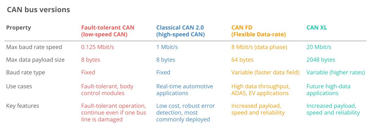 Classical CAN FD XL Variants canbus
16. FAQ Section
16.1 What is a car scan tool?
A car scan tool, also known as an automotive diagnostic tool, is an electronic device used to read and interpret data from a vehicle’s computer system. It helps technicians identify and diagnose issues with the engine, transmission, ABS, and other systems.
16.2 Why is training important for using car scan tools?
Training is essential because modern car scan tools offer a wide range of features and functionalities. Proper training enables technicians to use these tools effectively, interpret the data accurately, and diagnose issues efficiently.
16.3 What are the benefits of remote technician education?
Remote technician education offers flexibility, convenience, and cost-effectiveness. Technicians can learn at their own pace, from anywhere, and access a wide range of courses and resources.
16.4 How can network topology visualization help in car diagnostics?
Network topology visualization provides a graphical representation of the vehicle’s communication network. This helps technicians quickly identify communication faults, understand data flow, and isolate problem areas.
16.5 What is a CAN bus, and why is it important?
CAN (Controller Area Network) bus is a communication protocol used in vehicles to allow different electronic control units (ECUs) to communicate with each other. It’s crucial for coordinating various functions, such as engine control, braking, and safety systems.
16.6 What is a DBC file, and how is it used in car diagnostics?
A DBC (CAN database) file is a text file that contains information for decoding raw CAN data. It’s used by diagnostic tools to translate CAN frames into human-readable signals, such as temperature, speed, and pressure.
16.7 How can I choose the right car scan tool for my needs?
Consider the following factors: the types of vehicles you’ll be working on, the features you need, your budget, and the availability of training and support.
16.8 What are the common challenges faced when using network topology visualization tools?
Data overload, inaccurate or incomplete data, and lack of expertise are common challenges. Proper training and adherence to best practices can help overcome these challenges.
16.9 What career opportunities are available for technicians skilled in using car scan tools and network topology visualization?
Technicians with these skills can work as automotive diagnosticians, service technicians, shop foremen, or even trainers and consultants.
16.10 How can CAR-SCAN-TOOL.EDU.VN help me enhance my skills in car diagnostics?
CAR-SCAN-TOOL.EDU.VN offers comprehensive training programs, expert instructors, hands-on experience, and flexible learning options to help you master the art of car diagnostics using OEM tools and network topology visualization.
Ready to elevate your diagnostic skills? Contact CAR-SCAN-TOOL.EDU.VN now to explore our remote training programs and become an expert in network topology visualization! Dial +1 (641) 206-8880 or visit CAR-SCAN-TOOL.EDU.VN today! Our office is located at 555 Automotive Way, Suite 100, Los Angeles, CA 90017, United States. Secure your future with premier automotive diagnostics training!